Tel:+86-512-53640771-125 E-mail: export@alumag.com.cn
- All
- Product Name
- Product Keyword
- Product Model
- Product Summary
- Product Description
- Multi Field Search

Views: 0 Author: Site Editor Publish Time: 2026-07-23 Origin: Site


Wall thickness dictates the structural integrity and manufacturability of extruded components. Engineers face a constant challenge when designing these parts. You must balance load-bearing capacity with material efficiency. Poor thickness specification carries significant operational risks. Over-engineering leads to excessive material weight and unnecessary mass. Under-engineering risks catastrophic structural failure, severe warping during production, and rejected batches. Specifying the correct dimensions solves these problems. Wall thickness acts as the primary variable controlling final part strength. It also determines viability during the extrusion, cooling, and post-processing phases. Understanding how metal flows through a die helps you optimize your designs. You can achieve maximum rigidity without sacrificing production speed. This guide explores the physics of wall thickness. You will learn how to engineer aluminum extrusion profiles for optimal performance and reliable manufacturing.
Strength vs. Weight Trade-off: Increasing wall thickness directly improves load-bearing capacity and reduces bending, but yields diminishing returns relative to material cost, weight, and extrusion speed.
Metal Flow & Die Resistance: Thicker walls alter metal flow dynamics through the die. While they reduce friction, they require precise die bearing designs to balance flow speeds with thinner adjacent sections.
The Dynamics of Shrinkage: Thicker sections accumulate greater thermal mass and take longer to cool, exerting stronger warping forces as they shrink during quenching.
Tolerance Standards: Standard wall thickness tolerances typically range from ±0.005 to ±0.030 inches; extreme variations in wall thickness make holding tight tolerances (standard ±0.010 inches) exceptionally difficult.
Engineers measure extrusion strength using yield strength, tensile strength, and deflection resistance. Yield strength defines the stress point where permanent deformation occurs. Tensile strength marks the ultimate breaking point under tension. Deflection resistance measures stiffness under applied loads. Wall thickness contributes directly to all three metrics. Thicker walls provide more cross-sectional area to distribute mechanical stress. This reduces the localized strain on the metal matrix. However, simply adding thickness does not guarantee a proportional increase in overall part strength. You must place the material strategically to maximize structural efficiency. We evaluate success based on how well the profile resists operational loads without adding unnecessary mass.
To accurately assess the structural viability of a profile, we rely on specific measurement techniques on the shop floor. These methods confirm that the theoretical thickness translates into actual physical strength.
Tensile testing of extruded samples to verify yield points.
Three-point bend tests to measure deflection under simulated loads.
Cross-sectional analysis using optical comparators to verify material distribution.
Hardness testing across different thickness zones to ensure uniform quenching.
Added material thickness changes structural rigidity in non-linear ways. Increasing the wall thickness boosts the cross-sectional moment of inertia. The moment of inertia governs how a shape resists bending and deflection. A modest increase in wall thickness can exponentially reduce deflection. For example, adding 10% more thickness to an outer flange drastically improves stiffness. The material sits further from the neutral axis. This placement maximizes the geometric resistance to bending forces. Engineers use this mathematical relationship to optimize profiles. You can achieve high load-bearing capacity without adding excessive dead weight to the structure.
Consider how specific thickness adjustments impact deflection in a standard rectangular tube under a center point load. The relationship between added material and structural gain is rarely 1:1.
Base Wall Thickness (inches) | Thickness Increase | Deflection Reduction (%) | Weight Penalty (%) |
|---|---|---|---|
0.062 | +0.010 | 18% | 15% |
0.125 | +0.020 | 22% | 16% |
0.250 | +0.050 | 28% | 20% |
Wall thickness dictates strength differently depending on the profile category. A solid aluminum extrusion relies entirely on its dense cross-section for rigidity. Solid shapes handle high localized compression loads exceptionally well. However, they suffer from poor weight-to-strength ratios in bending applications. Hollow profiles offer superior torsional and bending strength. The walls sit far from the center of mass. This geometric advantage allows hollow shapes to resist twisting forces. You must evaluate geometry versus mass when selecting a profile type. Strategic wall placement often outperforms sheer material volume.
When designing a solid shape, every ounce of aluminum sits relatively close to the center. This limits the moment of inertia. In contrast, a hollow tube pushes the mass outward. The outer walls do the heavy lifting during bending or twisting. This is why structural frames almost exclusively use hollow or semi-hollow designs. Solid bars are reserved for applications requiring heavy machining or extreme localized impact resistance.
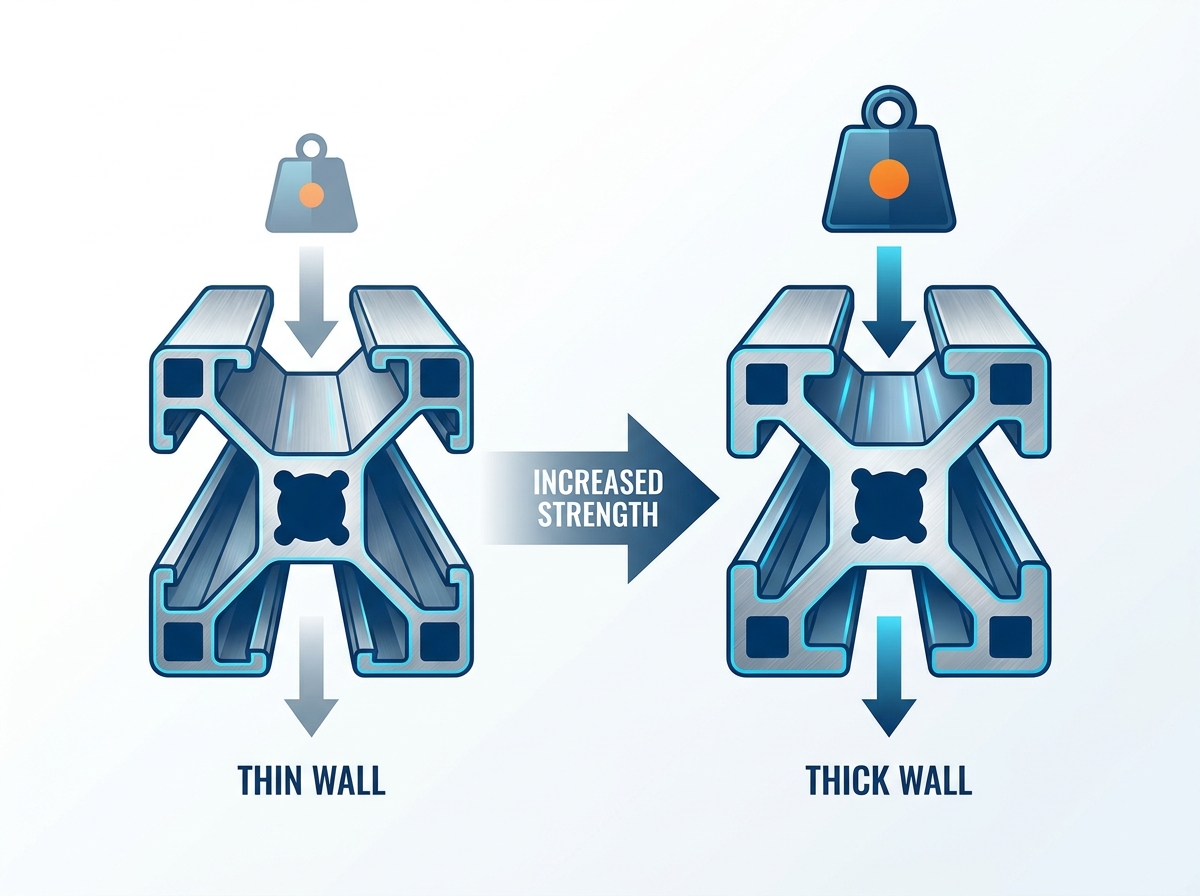
Strength on paper must translate to manufacturability on the press. A perfectly engineered cross-section means nothing if it cannot be extruded reliably. Manufacturing realities dictate what you can actually produce. Wall thickness variations create complex challenges inside the extrusion press. You must account for metal flow, friction, and thermal dynamics. Ignoring these factors leads to high scrap rates and failed production runs. Tool designers and extrusion operators evaluate profiles based on extrudability. They look for uniform walls and balanced mass distribution.
Aluminum flows faster through wider die openings than narrow ones. Thicker walls present less resistance to the pressurized aluminum billet. Thinner walls create high friction and restrict metal flow. This difference causes uneven flow velocities across the profile cross-section. Tool designers use varying bearing lengths to control this phenomenon. A longer bearing creates more friction to choke the flow in thick areas. A shorter bearing speeds up metal flow in thin areas. Balancing these flow rates prevents the profile from twisting or bowing as it exits the die onto the run-out table.
Die correctors spend hours adjusting these bearing lengths. If a thick flange flows too fast, it will pull the thinner web along with it, causing ripples or tearing. The corrector must file the bearing on the thin section to speed it up, or peen the bearing on the thick section to slow it down. This manual tuning is difficult and time-consuming. Designing uniform walls eliminates this problem entirely.
Extreme wall thicknesses heavily influence press speed and throughput. Very thin walls require immense extrusion force to push the metal through the die. This limits the maximum speed of the press and increases production time. Conversely, very thick profiles also limit extrusion speed due to heat dissipation bottlenecks. Thick sections generate massive amounts of friction-induced heat. The metal must cool sufficiently before handling. Pushing thick profiles too fast causes surface tearing and metallurgical defects. You must find the optimal thickness to maximize throughput and maintain surface quality.
Press operators monitor the exit temperature constantly. If a heavy-walled profile exits too hot, the surface will blister and tear. The operator has no choice but to slow the ram speed down. This reduces the pounds-per-hour output of the press. Slower output means higher manufacturing costs. A well-balanced profile allows the operator to run the press at optimal speeds without risking surface defects.
Quenching physics play a massive role in extrusion quality. Aluminum profiles undergo rapid cooling as they exit the press. Thicker areas retain heat much longer than thin areas. This creates localized thermal zones across the profile. As the metal cools, it shrinks. The thicker, hotter sections exert high shrinking forces on the adjacent, faster-cooling thin sections. This differential contraction causes severe warping, bowing, and twisting. Managing these contractile forces requires precise quenching strategies. Engineers must design profiles that cool as evenly as possible to maintain dimensional stability.
When a profile warps during quenching, it often exhibits specific types of distortion based on the thickness imbalance.
Bowing: The profile curves along its longitudinal axis, usually pulling toward the thicker, slower-cooling side.
Twisting: The profile spirals along its length due to asymmetrical mass distribution.
Oil Canning: Thin webs buckle and wave between thicker flanges.
Flange Flare: The outer edges of a U-channel or I-beam splay outward or pinch inward.
Designing a reliable custom aluminum extrusion profile requires actionable engineering frameworks. You cannot rely on guesswork when specifying dimensions. Start by analyzing the primary load paths and structural requirements. Determine the minimum thickness needed for mechanical fastening and assembly. Next, evaluate the profile for extrudability and metal flow balance. Apply specific design rules to manage transitions and corners. Following established guidelines ensures your design moves smoothly from CAD software to the production floor.
Maintain uniform wall thickness wherever possible. Uniformity stands as the golden rule of extrusion design. Consistent walls ensure even metal flow through the die. They promote predictable cooling rates during the quenching process. This stability translates directly to tight dimensional control and straight profiles. When walls are uniform, the press operator can run the machine faster. Die wear remains balanced, extending tooling life. If you must vary the thickness, keep the variations symmetrical. Symmetrical designs prevent the profile from pulling to one side during extrusion.
Symmetry does not just mean mirroring the left and right sides. It means balancing the mass across the entire cross-section. If you have a heavy screw boss on the top left, try to place a corresponding mass on the bottom right. This balances the thermal load and keeps the profile straight on the cooling bed.
Variable thickness is sometimes unavoidable in complex designs. When you must mix thick and thin walls, follow the rule of transitions. Keep adjacent thickness ratios within a 1:2 limit. Never exceed a 1:3 ratio under any circumstances. Abrupt changes in thickness cause severe stress concentrations. They also disrupt metal flow and cause cooling distortion. Use generous corner radii and fillets to blend thick and thin sections. A smooth taper allows the aluminum to transition without tearing. Proper fillets distribute mechanical stress and prevent cracking during service.
Thin Wall Dimension | Maximum Adjacent Thick Wall | Recommended Fillet Radius |
|---|---|---|
0.062 inches | 0.125 inches (1:2 ratio) | 0.031 inches |
0.125 inches | 0.250 inches (1:2 ratio) | 0.062 inches |
0.250 inches | 0.500 inches (1:2 ratio) | 0.125 inches |
Practical limits of wall thickness depend heavily on your alloy choice. Highly extrudable alloys like 6063 allow for very thin walls. You can often push 6063 down to 0.040 inches in small profiles. Structural alloys like 6061-T6 contain more alloying elements like magnesium and silicon. These elements increase flow resistance inside the die. Therefore, 6061 requires thicker minimum walls, typically starting around 0.062 inches. Press capacity also dictates maximum thickness. A small press cannot generate enough force to push a massive, thick-walled solid shape. Always verify alloy limits with your manufacturing partner.
The temper designation also plays a role. Achieving a T6 temper requires a rapid quench. If the walls are too thick, the core of the metal will not cool fast enough to lock the alloying elements into solution. This results in lower mechanical properties in the center of the profile. You must size the walls to allow for complete through-thickness quenching.
Wall thickness decisions carry heavy commercial implications. You must evaluate the overall value of your design choices. Adding material increases strength but drives up raw material consumption. Reducing material saves weight but may increase tooling complexity and scrap rates. You must analyze the complete manufacturing lifecycle. Consider extrusion speed, die maintenance, and quality assurance costs. A balanced profile delivers the best return on investment. It meets structural requirements while remaining highly manufacturable and cost-efficient.
Calculate the return on investment for adding thickness. Aluminum extrusions are typically sold by weight. Every millimeter of added wall thickness increases the linear weight of the profile. This directly inflates the per-unit raw material cost. You must balance this weight penalty against structural gains. Use structural geometry to build strength instead of raw mass. Moving material away from the neutral axis increases rigidity without adding weight. Smart geometric design reduces per-unit costs while maintaining or exceeding performance specifications.
For high-volume production runs, even a fraction of an inch in excess thickness adds up to thousands of pounds of wasted aluminum. Engineers must ruthlessly trim non-structural mass. Hollow out thick sections where possible. Use internal ribs to support wide, flat spans instead of thickening the entire wall.
Pushing extreme wall variations through a die accelerates tool wear. Highly thin sections create massive friction against the die steel. This friction generates heat and gradually washes away the bearing surfaces. Unbalanced profiles force the die to work harder to control metal flow. This increases maintenance frequency and drives up tooling costs. A well-designed profile with uniform walls extends die longevity significantly. The metal flows smoothly, reducing abrasive wear. Protecting the die ensures consistent part quality over long production runs.
When a die wears out, the profile dimensions drift out of tolerance. The manufacturer must pull the die, send it to the tool room for correction, and run a new trial. This downtime costs money. Designing for manufacturability keeps the die in the press longer and reduces tooling-related delays.
Unbalanced profiles drastically increase the likelihood of manufacturing defects. Adjacent thickness variations cause twist, bow, and dimensional instability. These issues lead to out-of-tolerance parts and high scrap rates. High scrap rates destroy production efficiency and extend lead times. Quality control teams must spend more time inspecting and rejecting bad parts. Designing for manufacturability minimizes these risks. A balanced, uniform profile extrudes straight and true. It passes quality inspections easily, keeping your production schedule on track and minimizing wasted material.
Common scrap causes directly related to poor thickness specification include:
Torn surfaces on thin webs due to excessive extrusion speed.
Blistering on heavy sections due to inadequate cooling.
Dimensional collapse of hollow chambers during stretching.
Angular distortion where thick flanges meet thin webs.
Establish baseline expectations for dimensional accuracy early in the design phase. You must understand what the extrusion process can realistically achieve. Tight tolerances require precise die manufacturing and strict process control. Loose tolerances allow for faster production but may cause assembly issues. Quality assurance teams evaluate profiles based on industry standards. They measure wall thickness, straightness, twist, and angularity. Compliance ensures the final product functions correctly in its intended application.
Industry standard tolerances dictate the acceptable deviation band for wall thickness. These tolerances typically range from ±0.005 inches to ±0.030 inches. The standard nominal baseline for general extrusions is ±0.010 inches. Nominal wall thickness directly dictates the tolerance band. Thicker walls generally carry wider tolerance allowances. Larger overall profile dimensions also increase the acceptable deviation. Extreme variations in wall thickness make holding tight tolerances exceptionally difficult. The uneven cooling and flow dynamics disrupt dimensional stability. Always consult standard tolerance tables when specifying critical dimensions.
If your assembly requires a slip fit or a press fit, you must account for these tolerance bands. Do not design a mating part assuming the extrusion will be perfectly nominal. Design the joint to accommodate the maximum allowable material condition.
Quality assurance processes verify wall thickness compliance and structural integrity. Inspectors use cross-sectional calipers to measure exposed walls. For complex hollow shapes, they utilize coordinate measuring machines to map the internal geometry. Ultrasonic testing helps detect internal voids or inclusions within thick sections. Technicians also cut cross-sections and etch them to examine the grain structure. These rigorous inspections ensure the profile meets all engineering specifications. Verifying structural integrity prevents field failures and guarantees reliable performance under load.
Inspection Tool | Measurement Target | Application |
|---|---|---|
Micrometer / Caliper | External wall thickness | Quick checks on the shop floor |
Coordinate Measuring Machine (CMM) | Internal geometry and complex profiles | First article inspection and tight tolerance verification |
Ultrasonic Gauge | Hidden wall thickness in closed hollows | Non-destructive testing of structural tubes |
Moving a profile from CAD software to physical production involves significant risk. The most common points of failure occur during the initial die trials. Theoretical designs often behave unpredictably under extreme heat and pressure. Flow imbalances cause the profile to exit the die distorted. Quenching forces warp the metal beyond acceptable limits. Identifying these risks early prevents costly tooling revisions. You must anticipate how the metal will react to your specific wall thickness choices.
Thin walls present unique vulnerabilities during both extrusion and application. During production, extremely thin sections risk tearing as they pass through the die bearing. The high friction can literally pull the aluminum apart. In application, thin walls lack sufficient material for secure thread engagement. Fasteners can easily strip out under vibration or load. Thin sections are also highly vulnerable to localized buckling under impact loads. You must reinforce thin walls with ribs or specify thicker localized pads for mechanical fastening points.
If you must tap a hole in a thin wall, consider using a flow-drilling process or installing a rivet nut. These methods provide the necessary thread engagement without requiring you to thicken the entire profile wall.
Heavy walls require aggressive strategies to mitigate shrinkage and distortion. Manufacturers use localized air or water spray quenching to control cooling rates. Directing high-velocity air at thick sections speeds up their cooling to match thinner areas. Post-extrusion stretching straightens the profile and relieves internal residual stresses. This stretching process locks in dimensional stability. Optimized artificial aging cycles further stabilize the mechanical properties. Proper heat treatment ensures the thick sections achieve the required yield strength without compromising the overall shape.
For massive solid profiles, a standing wave water quench is often necessary. The profile passes through a high-volume water bath immediately after exiting the press. This rapid cooling prevents the grain structure from growing too large, ensuring high strength and uniform hardness.
Conduct a comprehensive design-for-manufacturability review on your current CAD models.
Adjust adjacent wall thickness ratios to stay within the recommended 1:2 limit.
Request a tooling consultation to evaluate metal flow dynamics and die bearing strategies.
Order short prototype runs to validate structural strength assumptions and cooling stability.
A: Minimum thickness depends on the alloy and press size. Highly extrudable alloys like 6063 can achieve walls as thin as 0.040 inches on small presses. Structural alloys like 6061 require thicker minimums, typically around 0.062 inches, due to higher flow resistance. Profile size also dictates the absolute minimum achievable thickness.
A: Wall thickness directly correlates to material weight, which drives raw material costs. Thicker walls use more aluminum per foot. Extreme thickness variations also slow down press speeds and accelerate die wear. This increases production time and tooling maintenance, raising the overall per-unit cost.
A: Uneven walls cool at different rates during quenching. Thicker sections retain heat longer and shrink more forcefully as they cool. This differential contraction exerts massive stress on the adjacent, faster-cooling thin sections. The resulting internal forces cause the profile to twist, bow, or warp.
A: No. While solid profiles offer high compressive strength due to raw mass, hollow profiles often provide superior bending and torsional strength. Hollow shapes place material further from the neutral axis. This engineered structural geometry increases the moment of inertia, resisting deflection better than a solid bar of equal weight.
A: The industry standard nominal tolerance is generally ±0.010 inches. However, acceptable deviation ranges from ±0.005 inches to ±0.030 inches. The exact tolerance depends on the profile's overall size, the specific alloy, and the nominal wall thickness specified in the design.
A: Yes, adding physical bulk can increase overall load-bearing capacity. However, this is an inefficient trade-off. It adds significant dead weight and material cost. Upgrading to a stronger alloy temper, like moving from 6063-T5 to 6061-T6, usually provides better yield strength without the weight penalty.