Tel:+86-512-53640771-125 E-mail: export@alumag.com.cn
- All
- Product Name
- Product Keyword
- Product Model
- Product Summary
- Product Description
- Multi Field Search

Views: 0 Author: Site Editor Publish Time: 2026-07-21 Origin: Site


The inherent limitation of the extrusion process is straightforward. While it efficiently produces continuous 2D cross-sections at scale, modern engineering applications rarely rely on purely linear geometries. Pushing heated billet through a steel die creates uniform lengths of material. It cannot produce cross-axis holes, interrupted cuts, or varying wall thicknesses along the length of the part. This physical reality forces engineering teams to make specific manufacturing decisions early in the design phase.
Over-specifying or under-specifying secondary operations creates significant operational friction. Defaulting to CNC machining for every feature increases cycle times and adds unnecessary setup requirements. Conversely, avoiding secondary machining entirely leads to tolerance stacking issues, poor mating surfaces, and assembly failures in the field. Finding the exact point where raw profiles need precision intervention is a standard manufacturing challenge.
Evaluating when to transition raw material into precision-machined components requires a strict technical framework. By focusing on Design for Manufacturability (DFM), specific tolerance thresholds, and material yield rates, production teams optimize workflows. The goal is to maximize the geometric work done by the extrusion die and rely on secondary milling and turning only when physics and precision demand it.
Process Synergy: Aluminum extrusion establishes the bulk geometry and structural integrity, while CNC machining is reserved strictly for non-linear, high-precision, and cross-axis features.
Tolerance Thresholds: Standard extrusion tolerances (e.g., standard dimensional tolerances per Aluminum Association) are sufficient for many structural applications; CNC is required when tolerances drop below ±0.005 inches.
DFM Impact: Investing in a well-designed custom aluminum extrusion profile die can eliminate up to 80% of secondary machining requirements by integrating features like screw bosses and T-slots directly into the profile.
Cost Dynamics: The decision to machine depends heavily on production volume. High volumes justify complex extrusion dies to minimize CNC cycle times, whereas low volumes may favor simpler extrusions with heavier CNC reliance.
The primary mechanical advantage of the extrusion process lies in its ability to create continuous, uniform cross-sections with exceptional structural integrity. When heated aluminum is forced through a shaped die, the resulting grain structure aligns longitudinally. This provides excellent strength-to-weight ratios along the axis of the profile. The process works exceptionally well for structural framing, heat sinks, and architectural components.
Cost efficiency is another major success criterion. Extrusion places bulk material exactly where it is needed without the massive chip-making waste associated with hogging out parts from solid rectangular billets. When you specify aluminum extrusion profiles, you achieve near-net shape in a single press cycle. Modern extrusion presses deliver standard surface finishes and baseline dimensional accuracies that are perfectly acceptable for a wide range of industrial and commercial applications straight off the run-out table. You get functional parts with minimal secondary handling.
The speed of production also outpaces machining. Once a die is proven, a press can push thousands of feet of material per shift. This throughput makes extrusion the undisputed choice for linear bulk material generation. The physical properties of the extruded metal, especially when properly quenched and artificially aged, meet stringent structural requirements across multiple industries.
Despite its efficiency, extrusion is bound by the physics of continuous flow. It is physically impossible to create interrupted cuts, cross-axis holes, or variable wall thicknesses along the extrusion axis using only a die. If a component requires a transverse slot for a sensor or a tapped hole for a fastener, the die cannot generate these features. The profile remains uniform from end to end until a secondary process intervenes.
Standard extrusion tolerances also present limitations in high-precision mating assemblies. While acceptable for general construction, standard die tolerances cannot meet the strict requirements of aerospace components, fluid-tight hermetic sealing surfaces, or optical mounts. The extrusion process naturally introduces slight profile twist, bow, and angularity over long lengths as the metal cools and is stretched. Raw extrusion cannot self-correct these micro-deviations. These deviations stack up and cause interference in tight assemblies.
Surface finish requirements can also exceed raw extrusion capabilities. While the finish is smooth, it contains longitudinal grain lines and minor die marks. Applications requiring mirror finishes, ultra-low Ra values for thermal contact, or specific cosmetic textures cannot rely solely on the raw extruded surface. Mechanical intervention is required to alter the surface topography.
A common misconception in product development is that every extruded part requires post-extrusion CNC machining to be functional. This assumption drives up unnecessary manufacturing overhead. The reality is that many profiles are designed to function perfectly as raw, cut-to-length stock. Smart engineering leverages the die to do the heavy lifting.
The economic boundary is clear. Raw profiles serve perfectly for structural frames, solar panel brackets, conveyor guides, and outdoor conduit without any secondary operations. By utilizing integrated features like snap-fits, hinge joints, and captive nut channels, engineers design complex assemblies that snap or bolt together directly off the saw. This completely bypasses the machine shop and accelerates assembly times.
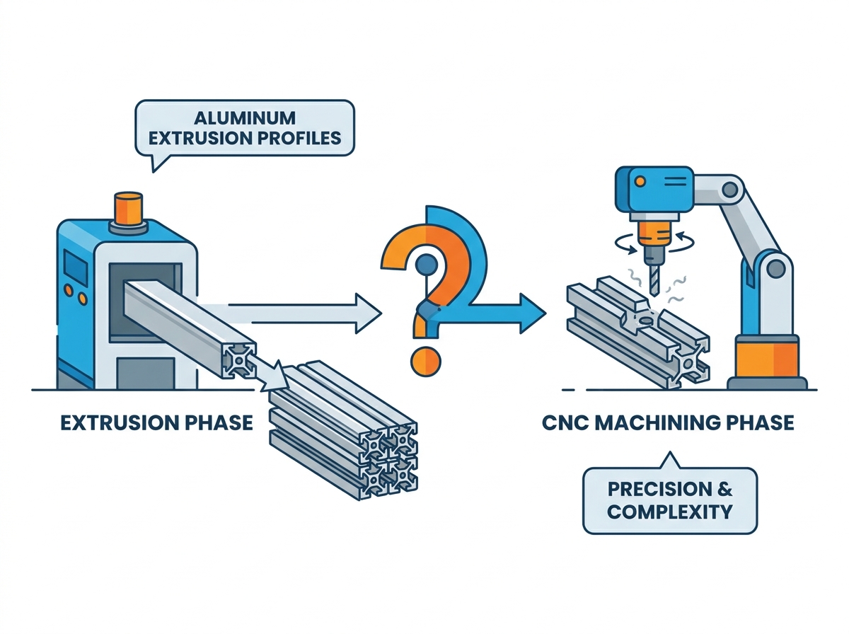
The most absolute trigger for secondary machining is the need for tight tolerances. Standard extrusion tolerances generally range from ±0.008 inches to ±0.020 inches, depending on the overall dimension size and wall thickness. While this is adequate for a structural bracket, it is entirely insufficient for precision mechanical interfaces. CNC milling and turning centers routinely hold tolerances of ±0.001 inches down to ±0.0005 inches.
Specific use cases mandate this level of precision. If a profile requires a press-fit bearing, the bore must be interpolated on a CNC mill to guarantee the exact diameter and roundness. Hermetic sealing surfaces for O-rings and precision linear guide rails require the absolute flatness and dimensional accuracy that only a rigid machine tool can provide. You cannot rely on a stretched piece of metal to hold a bearing press-fit.
CNC machining becomes necessary when functional geometry must break the continuous profile. Any feature that operates perpendicular to the direction of the extrusion push requires secondary intervention. This is the most common reason extruded parts end up on a milling table. The die simply cannot stop and start material flow mid-push.
Common required features that cannot be extruded include:
Tapped and threaded holes for assembly fasteners.
Transverse slots for cable routing or sensor mounting.
Countersinks and counterbores for flush screw heads.
Interlocking tabs for complex multi-part enclosures.
Side-drilled ports for fluid or air manifolds.
Integrating non-circular features requires milling. Machining oblong slots for adjustable mounting, square-shaped cutouts for digital displays, and complex interior pocket recesses for PCB boards all demand precise CNC toolpaths. The spindle must remove material where the die left it.
When extruded lengths are cut on a production saw, the resulting ends may have slight angularity deviations or rough cut marks. CNC machining is frequently used to face-mill these ends, ensuring perfect perpendicularity and flat mating interfaces. This is critical in fluid-handling manifolds or structural frames where angular deviation would cause the entire assembly to skew out of alignment.
Localized surface finish improvements also trigger CNC operations. In high-performance thermal management, the base of an extruded heatsink may require a fly-cutting operation to achieve a very low Ra value. This ultra-smooth surface maximizes contact area for thermal paste application. It significantly improves heat transfer efficiency compared to the raw extruded finish.
In many heavy-duty applications, engineers use a solid aluminum extrusion as near-net-shape stock instead of purchasing standard rectangular billet. This approach is highly strategic. If a final part resembles a thick L-bracket or a heavy U-channel, starting with a solid extruded shape that closely matches the final footprint drastically reduces the amount of material that needs to be removed.
The CNC machine is then utilized to cut deep pockets, internal cavities, or complex 3D contours into this solid profile. This method significantly reduces material waste and spindle time compared to machining the exact same geometry from a solid rectangular block of aluminum. You buy less raw material and spend less time turning it into chips.
In aerospace, automotive, and high-performance robotics, weight is a strict constraint. However, an extrusion die must maintain uniform wall thickness along the entire length of the part. If only a specific segment of the part requires thick walls for mounting, the rest of the length carries unnecessary dead weight. You cannot extrude a part that is thick at the ends and thin in the middle.
Secondary CNC machining solves this by aggressively pocketing and thinning out non-critical sections of the extrusion. This localized weight reduction allows engineers to save mass exactly where it is not needed. It preserves the thick structural integrity at high-stress mounting points and load-bearing joints. The result is a highly optimized, lightweight component.
The most effective way to reduce manufacturing overhead is to eliminate secondary operations before the first piece of metal is cut. A rigorous DFM framework focuses on migrating machined features directly into the die design. Every feature that can be pushed through the die is a feature that does not require spindle time. You want the press to do the work, not the mill.
Practical examples of this migration include replacing individually drilled and tapped holes with continuous extruded screw bosses. Instead of milling long channels for wire routing, engineers design extruded T-slots. Snap-fit joints can be integrated into the profile walls, eliminating the need for complex machined interlocking tabs. Developing a custom aluminum extrusion profile die requires upfront engineering. The long-term savings realized by eliminating CNC cycle times on thousands of parts quickly justify the initial tooling investment.
The choice of extrusion alloy heavily impacts the success and speed of secondary CNC operations. Not all aluminum alloys behave the same way under a cutting tool. 6063 aluminum is highly favored for its excellent extrudability, allowing for intricate die shapes and superior surface finishes. However, it is relatively soft and gummy to machine. It often leads to long, stringy chips that wrap around tooling and cause poor milled finishes.
Conversely, 6061 aluminum is the standard structural alloy. It forms much better chips during CNC operations, allowing for faster feed rates and cleaner surface finishes. It cannot be extruded into shapes quite as complex as 6063. 6005A offers a middle ground, providing good structural properties and decent machinability. Specifying the correct temper, such as T6, is vital to optimize material hardness. This ensures the metal shears cleanly rather than tearing during CNC cutting.
Engineering teams must constantly analyze the break-even point between tooling complexity and machining time. Does it make sense to pay for a highly complex, multi-hollow extrusion die, or is it more efficient to use a simpler solid die and machine the internal cavities later? This is a core DFM question.
Highly intricate, thin-walled hollow dies are harder to cut and have shorter lifespans due to higher extrusion pressures and die wear. If production volumes are low, it is often more economical to use a simpler, robust die and rely on CNC machining to achieve the final complex geometry. For high-volume automotive or consumer electronics production, investing in complex multi-hollow dies is mandatory to eliminate the bottleneck of CNC cycle times. Predictable CNC tool wear is easier to manage in low volumes, but die maintenance becomes the priority in mass production.
The financial math shifts dramatically depending on the production run size. For low-volume runs or early-stage prototyping, the most cost-effective strategy is utilizing standard, off-the-shelf extrusions and relying heavily on CNC machining to achieve custom features. The high variable cost of machine time is offset by avoiding the fixed cost of custom die creation. You get parts faster without tooling delays.
High-volume production demands the exact opposite approach. When manufacturing tens of thousands of units, investing heavily in custom dies to achieve near-net shape is imperative. The goal is to reduce CNC operations to mere seconds per part. A quick face mill and two tapped holes should be the maximum secondary work required. In high volumes, saving thirty seconds of cycle time per part translates to massive financial savings.
A thorough cost-benefit analysis requires breaking down fixed versus variable costs. Fixed costs include the engineering of extrusion dies, the fabrication of CNC workholding fixtures, and the programming time for the machine tools. Variable costs encompass the actual machine time, operator labor, cutting fluids, and material yield. You must track every minute a part sits in a machine.
Evaluating the product lifecycle means amortizing the fixed tooling costs over the expected volume. As volume increases, the strategy must shift toward maximizing die complexity to drive down the variable costs of CNC operator labor and spindle time. You want the machine operators loading and unloading parts as fast as possible, not waiting on long roughing cycles.
Material removal has both environmental and financial impacts. Every cubic inch of aluminum turned into chips represents wasted material and lost energy. Evaluating the buy-to-fly ratio—the weight of the raw material purchased versus the weight of the final finished part—is critical for efficient manufacturing.
Using extruded profiles as near-net-shape stock drastically improves this ratio compared to machining from a solid block. Even when secondary CNC operations are extensive, starting with a profile that already matches the outer boundary of the final part minimizes material waste. It reduces tool wear and shortens roughing cycles. This hybrid approach maximizes the yield rate of the raw aluminum.
Manufacturing Strategy | Ideal Production Volume | Initial Fixed Costs | Variable Per-Part Costs | Best Application Use Case |
|---|---|---|---|---|
Extrusion Only | High | Moderate | Very Low | Structural frames, continuous brackets, heat sinks. |
Standard Extrusion + Heavy CNC | Low to Medium | Low | High | Prototyping, specialized aerospace mounts, low-run custom parts. |
Custom Extrusion + Light CNC | High | High | Low | Automotive components, consumer electronics enclosures, mass production. |
Securing long, thin-walled aluminum profiles in standard CNC vises is notoriously difficult. Standard hard jaws apply concentrated pressure that can easily cause deformation, bowing, or outright crushing of hollow profiles. Machining long parts that overhang the machine table leads to severe chatter and vibration. This destroys surface finishes and breaks endmills.
Mitigation strategies require specialized workholding. Custom-machined soft jaws that encapsulate the specific profile shape distribute clamping forces evenly, preventing crush damage. For flat extrusions, vacuum fixtures provide excellent hold-down force without side pressure. For highly complex or exceptionally long parts, manufacturers utilize dedicated multi-axis long-bed profile machining centers designed specifically to support and machine extrusions over several meters in length.
The extrusion process, followed by rapid water or air quenching, introduces significant residual stresses into the aluminum grain structure. When a CNC machine removes material asymmetrically—such as milling a deep channel down one side of a profile—these internal stresses are released. This release causes the previously straight profile to suddenly warp, bow, or twist on the machine table.
To prevent this, engineers must specify stress-relieved tempers, such as Tx511. The "511" designation indicates that the profile was mechanically stretched by a specific percentage after quenching to align the grain structure and relieve internal stress. Machinists must utilize optimized tool paths that balance material removal. Alternating cuts on opposing sides of the part keeps stress release symmetrical.
A significant cosmetic challenge arises when combining these two processes. There is a visual discrepancy between the raw extruded surface and the machined areas. Raw extrusion features longitudinal grain lines and minor die lines, whereas CNC machined surfaces display distinct circular tool marks. If left untreated, this contrast looks highly unprofessional on visible consumer parts.
Post-machining finishing requirements are necessary to achieve a uniform cosmetic appearance. Tumbling, bead blasting, or mechanical brushing blends the machined and extruded surfaces into a single, cohesive texture prior to anodizing or powder coating. Quality control must address chemical compatibility. CNC cutting fluids, residual tapping oils, and localized micro-burrs ruin the adhesion of chemical finishes. Strict pre-coat cleaning protocols, including alkaline washes and de-smutting baths, are mandatory to ensure anodizing dyes and powder coats adhere flawlessly to both the raw and machined surfaces.
Secondary machining is a strategic addition reserved for tight tolerances and non-linear features that extrusion physics cannot achieve. By understanding the capabilities gap between the die and the spindle, engineering teams optimize their parts for both performance and cost-efficiency.
Push maximum geometry into the extrusion die during the initial CAD phase to eliminate unnecessary milling operations.
Calculate the break-even volume for your specific part to determine if the upfront cost of a complex custom die outweighs the variable costs of heavy CNC machining.
Specify stress-relieved tempers like T6511 and appropriate alloys like 6061 if extensive secondary material removal is unavoidable.
Engage with a vertically integrated manufacturing partner capable of handling both the extrusion press and the CNC operations under one roof.
A: Yes, it is standard practice. Extruded aluminum is frequently machined to add precise features like tapped holes and flat mating surfaces. It is critical to select the right alloy and temper, such as 6061-T6, to ensure optimal chip formation, prevent material tearing, and extend tool life during the milling process.
A: Yes. By designing the die to include near-net-shape features like channels, heat fins, and screw bosses, you eliminate the need for the CNC machine to mill those geometries. This drastically reduces spindle cycle time and operator labor, lowering the overall cost per part in production runs.
A: Raw extrusion typically holds tolerances between ±0.008" and ±0.020", depending on the overall dimensions and wall thickness. CNC machining can tighten those tolerances down to ±0.001" or better. CNC is required for critical mating surfaces, bearing press-fits, and hermetic seals.
A: For production volumes, using a solid aluminum extrusion as near-net-shape stock is almost always cheaper. It significantly reduces material waste and allows for much faster machining times compared to hogging out a solid rectangular billet, improving the overall buy-to-fly ratio.
A: Use stress-relieved tempers like Tx511, which stretch the metal after quenching to align the grain. Ensure proper workholding with custom soft jaws to prevent crushing, and program balanced CNC tool paths that remove material symmetrically to prevent the release of residual stresses from bowing the part.