Tel:+86-512-53640771-125 E-mail: export@alumag.com.cn
- All
- Product Name
- Product Keyword
- Product Model
- Product Summary
- Product Description
- Multi Field Search

Views: 0 Author: Site Editor Publish Time: 2026-07-18 Origin: Site


Surface finishes are not dimensionally neutral. Failing to account for coating thickness during the design phase remains a primary cause of assembly failure in precision manufacturing. When engineers treat anodizing as a simple color addition, they ignore the physical reality of oxide layer growth. This oversight leads to significant operational risks, including rejected batches of parts, out-of-spec mating components, thread binding, and costly rework on the shop floor.
Controlling final tolerances requires a strict mathematical understanding of how the anodic layer develops. You must account for pre-anodize chemical material loss, execute precise CAD adjustments, and maintain clear communication with finishing partners regarding pre- and post-anodize specifications. By mastering the mechanics of electrochemical conversion, you can ensure your components fit perfectly on the assembly line every time, avoiding the scrap bin and keeping production schedules intact.
The 50/50 Rule: Anodizing is an electrochemical conversion process, not an additive plating. Approximately 50% of the anodic layer penetrates the base aluminum, while 50% builds up outward, altering final dimensions.
The Etching Factor: Chemical pre-treatments (etching) dissolve a small amount of raw metal prior to anodizing, which can offset or compound final dimensional changes depending on the process used.
Coating Type Dictates Variance: Type II (Standard) anodizing typically adds negligible build-up (0.0001" to 0.0003" per surface), whereas Type III (Hardcoat) can add significant thickness (0.001" or more per surface).
Geometry Matters: Anodizing increases outside dimensions (OD) while simultaneously shrinking inside dimensions (ID) and hole diameters across every exposed surface.
The Contact Exception: Areas blocked by racking fixtures (rack marks) receive no current and will not undergo conversion, leaving raw metal dimensions intact.
Specification Clarity: Engineering drawings must explicitly state whether the specified dimensional tolerances apply before or after the anodizing process.
Engineers often mistake anodizing for standard plating or painting. This fundamental misunderstanding leads to incorrect tolerance calculations on a custom aluminum extrusion profile. Unlike paint, which sits entirely on top of a surface, anodizing transforms the base material itself. You are not adding a layer of material from an external source; you are converting the existing aluminum into aluminum oxide through an electrochemical reaction.
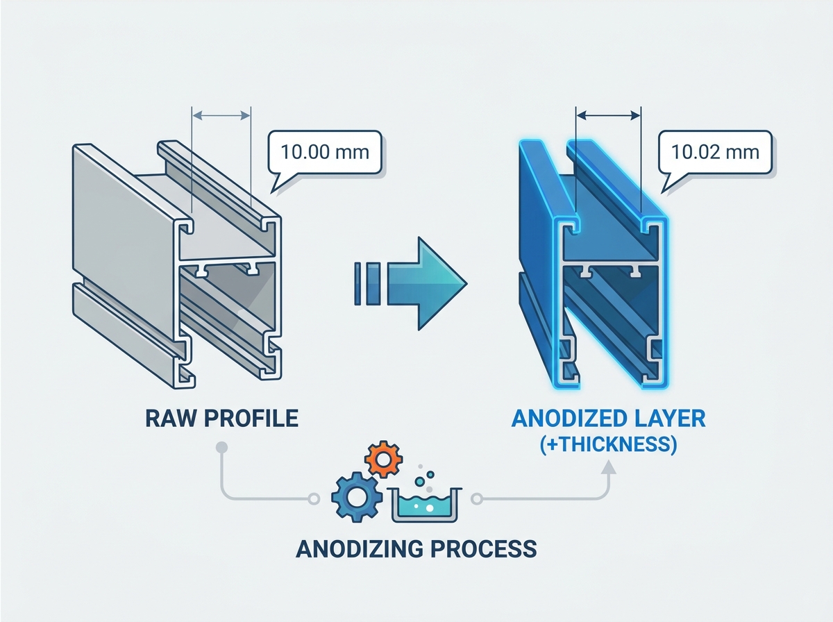
Anodizing is an electrochemical conversion process. The aluminum part is submerged in an acid electrolyte bath and subjected to a direct electrical current. This process consumes the base metal at the surface, converting it into a highly durable aluminum oxide. Because the oxide occupies more volume than the raw aluminum it replaces, the overall dimensions of the part change. If you measure a part with a micrometer before and after the tank, you will see a distinct difference in the physical size of the component.
When you apply a standard wet paint or powder coat, the entire thickness of that coating sits on top of the substrate. If you spray 0.002 inches of paint, the part grows by 0.002 inches per surface. Anodizing does not behave this way. The conversion process eats into the metal while simultaneously building up a porous oxide structure that is later sealed. Understanding this mechanism is the first step in preventing tolerance stack-up issues during final assembly.
The dimensional shift follows a standard baseline known as the 50/50 rule. When the aluminum oxide layer forms, half of the total coating thickness penetrates the existing raw metal, and the other half builds up outward from the original surface. If you specify a total anodic coating thickness of 0.002 inches, the part will experience an outward growth of 0.001 inches per surface. You must calculate this actual dimensional change based on the total requested coating thickness rather than assuming the entire coating sits on top of the metal.
Consider a precision shaft designed to fit into a bearing. If the shaft is machined exactly to the maximum allowable diameter before anodizing, the outward growth of the oxide layer will make the shaft too large to fit. The 50/50 rule dictates that you must machine the shaft undersized by an amount equal to half the total specified coating thickness. This mathematical adjustment must be calculated for every critical dimension on the print.
Before anodizing begins, parts undergo a chemical pre-treatment phase designed to clean the metal and remove minor surface imperfections. This step alters dimensions before the electrical current is even applied. The type of etch used by your finishing house will dictate how much raw material is lost.
Caustic Etching: Heavy caustic etching aggressively attacks the aluminum. It can strip away 0.0002 to 0.001 inches of raw metal per surface. This lowers the profile dimensions significantly, meaning the subsequent anodic growth might only bring the part back to its original machined size, or leave it undersized. Caustic etching is excellent for hiding die lines, but it is a nightmare for tight tolerances.
Acid Etching: Acid etching produces a matte finish while minimizing material removal. It preserves tight tolerances, making it the preferred pre-treatment for precision aluminum extrusion profiles where exact dimensions are critical. Acid etch typically removes less than 0.0001 inches of material, providing a much more stable baseline for the anodizing process.
Different series of aluminum react differently in the anodizing bath. For example, 6000 series alloys generally produce a uniform, dense oxide layer with predictable growth rates. These alloys are the standard for structural components and accept anodic coatings exceptionally well. In contrast, 7000 series alloys, which contain high levels of zinc, can dissolve faster in the acid bath. This subtly affects the growth rate and final density of the oxide layer, requiring slight adjustments in time and current density to achieve the desired thickness.
When working with 2000 series alloys, the high copper content presents another challenge. Copper does not anodize; it dissolves in the bath, leaving microscopic voids in the coating. This results in a softer, less wear-resistant finish and can cause unpredictable dimensional shifts. Always consult with your anodizer about the specific alloy you are using, as the bath parameters must be tuned to accommodate the chemical composition of the metal.
To properly design a solid aluminum extrusion, you must compare the dimensional impact of standard industry anodizing specifications, commonly defined by MIL-A-8625. The type of anodizing you select will dictate the severity of the dimensional changes and the level of CAD compensation required.
Anodizing Type | Typical Total Thickness | Outward Growth (Per Surface) | Primary Application |
|---|---|---|---|
Type II (Standard/Sulfuric) | 0.0002" to 0.0006" (5 - 15 µm) | 0.0001" to 0.0003" | Cosmetic finishes, moderate corrosion resistance. |
Type III (Hardcoat) | 0.002" (50 µm) | ~0.001" | High-wear, high-friction, extreme durability. |
Type I (Chromic Acid) | 0.00005" to 0.0002" | Negligible | Aerospace, fatigue-sensitive components. |
Type II anodizing is the most common finish. It typically yields a total thickness between 0.0002 and 0.0006 inches. Following the 50/50 rule, this results in just 0.0001 to 0.0003 inches of outward growth per surface. This minimal change makes Type II ideal for cosmetic finishes and moderate corrosion resistance where tight machining tolerances must be maintained without requiring significant CAD adjustments.
For most general-purpose applications, the dimensional shift caused by Type II anodizing falls within standard machining tolerances (typically +/- 0.005 inches). Unless you are dealing with press-fit bearings or precision dowel pins, you generally do not need to alter your machining dimensions for Type II coatings. However, you must still account for the pre-anodize etch, especially if the finishing house uses a heavy caustic process.
Type III hardcoat is engineered for durability. It typically requires a total thickness of 0.002 inches, though this is customizable. This results in approximately 0.001 inches of outward growth per surface. Consequently, it adds 0.002 inches to overall outside diameters and subtracts 0.002 inches from inside diameters. This finish is necessary for high-wear, high-friction applications, but it requires strict pre-machining compensation to ensure final parts remain within tolerance.
Hardcoat anodizing is performed at lower temperatures and higher current densities than Type II. This creates a denser, thicker oxide layer that provides excellent abrasion resistance. Because the dimensional shift is significant, machinists must cut the raw aluminum to specific pre-plate dimensions. Failure to do so will result in parts that cannot be assembled. Hardcoat is unforgiving; you cannot simply sand or grind it off if the part is oversized, as the coating is harder than the steel tools used to cut it.
Engineers need a reliable mathematical framework to adjust their designs for a custom profile. Understanding how outward growth affects different geometries is non-negotiable. You must evaluate every feature on the print and apply the correct offset based on the specified coating thickness.
Dimensional changes compound based on the number of surfaces involved. If a part has two parallel outside faces, the total dimensional increase is twice the outward growth. For a Type III hardcoat adding 0.001 inches per surface, a 2.000-inch wide block will measure 2.002 inches after finishing. You must machine the raw block to 1.998 inches to achieve the desired final dimension.
This compounding effect applies to all outside diameters. A cylindrical shaft with a nominal post-plate diameter of 1.000 inches must be turned down to 0.998 inches on the lathe. When measuring these parts on the shop floor, inspectors must use micrometers calibrated to the pre-plate dimensions. Providing a separate pre-plate drawing to the machine shop is the most effective way to prevent errors.
Internal geometries experience an inverse effect. Outward growth from the interior walls converges toward the center. This shrinks the effective diameter of holes, slots, and bores. A 1.000-inch bore subjected to Type III hardcoat will shrink by 0.001 inches on each side, resulting in a final internal diameter of 0.998 inches. To achieve a 1.000-inch final bore, the machinist must bore the hole oversize to 1.002 inches.
This shrinkage is particularly problematic for dowel pin holes and bearing journals. If a bearing requires a slight press fit, a bore that shrinks by 0.002 inches will make installation impossible. The bearing will bind, and forcing it will likely crack the brittle hardcoat layer. You must calculate the exact pre-plate bore size and verify it with go/no-go gauges before sending the batch to the anodizer.
Tapped holes present the highest risk for tolerance failure. The pitch diameter of a threaded hole is affected by a factor of four times the coating thickness due to the geometry of standard 60-degree thread angles. If a hardcoat adds 0.001 inches of thickness, the pitch diameter effectively shrinks by 0.004 inches. To compensate for Type III hardcoat buildup, machinists must use oversized taps, typically GH3 or GH5, to cut the initial threads larger than nominal.
Standard taps (GH2 or GH3) are designed for uncoated parts. When you run a standard tap into a hole that will receive a hardcoat, the resulting threads will be too tight to accept a standard fastener. The bolt will bind, and applying excessive torque will strip the threads or snap the fastener. By specifying oversized taps on the manufacturing drawing, you ensure the threads have enough clearance to accommodate the anodic growth. For highly critical threads, some shops prefer to mask the holes entirely, leaving them as raw aluminum.
Proper engineering documentation prevents miscommunication between the machine shop, the extruder, and the anodizer. Clarity on the print dictates success on the floor. If the drawing is ambiguous, the machinist will guess, and they will usually guess wrong.
The industry standard often defaults to "Dimensions apply AFTER finish." However, leaving this ambiguous on the drawing block invites disaster. If the machinist cuts the part to the nominal dimensions without knowing a thick hardcoat will be applied, the final part will be out of spec. Provide concrete blueprint notation conforming to ASME Y14.5 or ISO standards. Use explicit notes such as: "Dimensional limits apply after coating. Raw machining tolerances must account for 0.001 to 0.002 inch coating thickness."
Alternatively, you can provide two sets of dimensions: one for the raw machined part and one for the final coated part. This eliminates all guesswork. The machinist inspects the part against the pre-plate dimensions, and the quality control team inspects the final part against the post-plate dimensions. This dual-dimensioning strategy is highly recommended for complex aerospace and medical components.
Determine early whether to model parts at their pre-anodized dimensions or nominal post-anodized dimensions. For standard Type II anodizing, nominal modeling is usually sufficient. For Type III hardcoat applications, apply standard offsets directly in the CAD model for critical mating surfaces to ensure the CAM software generates the correct pre-plate toolpaths.
If you model the part at the final post-plate dimensions, the CNC programmer must manually apply negative stock allowances in the CAM software to cut the part undersized. This introduces a significant risk of human error. By modeling the part at the pre-plate dimensions, the CAM software automatically generates the correct toolpaths. You can then use the 3D model directly for machining, while the 2D drawing specifies the final coated dimensions for inspection.
When certain features cannot tolerate any dimensional shift, masking is a viable mitigation strategy. Critical mating surfaces, grounding points, or tight-tolerance bores can be masked off to prevent the anodic coating from forming. However, manual masking is labor-intensive. You must weigh the cost trade-offs of masking versus adjusting the initial machining tolerances to accommodate the coating.
Masking involves applying specialized tapes, liquid resists, or custom silicone plugs to the areas that must remain bare aluminum. This process is done by hand and adds significant time and cost to the finishing operation. Furthermore, masking lines are rarely perfect; there is always a slight bleed zone where the coating transitions to bare metal. If you can achieve the required tolerances by adjusting the machining dimensions, it is almost always more cost-effective than masking.
Even with perfect math, the physical limitations of the anodizing process can cause unexpected dimensional variations. Anticipating these risks ensures better quality control and reduces the scrap rate.
Anodic coatings grow perpendicular to the surface. On sharp 90-degree outside corners, the coating diverges. This creates a micro-void or a brittle, thick edge known as the corner defect. To ensure uniform coating growth and prevent edge chipping, implement minimum corner radii. Recommend a 0.015-inch radius for a 1 mil thickness, and a 0.030-inch radius for a 2 mil thickness.
If you leave outside corners sharp, the hardcoat will form a fragile ridge that easily chips off during handling or assembly. This chipping exposes the raw aluminum underneath, compromising the corrosion resistance and aesthetic appearance of the part. By breaking all sharp edges with a chamfer or radius during the machining phase, you provide a smooth transition for the oxide layer to grow uniformly.
Electrical contact must be established via racks or wire ties during the anodizing process. Because the current flows through these physical connection points, no anodization occurs exactly where the rack touches the metal. These contact points result in localized zones of raw metal dimensions. Strategically place rack marks on non-critical, hidden surfaces to protect critical tolerance paths and aesthetic requirements.
You must communicate the acceptable locations for rack marks to your anodizer. If you do not specify these locations, the operator will clamp the part wherever it is most convenient, which might be right in the middle of a critical sealing surface. Add a specific note to the drawing indicating where rack marks are permissible. For example: "Rack marks permitted only on inside diameter of bore A."
Anodizing is sensitive to environmental factors. Bath temperature, current density, chemical concentrations, and time in the tank introduce micro-variations, typically around ±0.0002 inches, even within the same batch. Advise your engineering team to set realistic tolerance windows. Avoid demanding ±0.0001-inch tolerances on hardcoated features, as the process inherently fluctuates beyond that margin.
If you require extreme precision, you must machine the parts slightly oversize, apply the hardcoat, and then perform a secondary grinding or honing operation to achieve the final dimension. This is common practice for hydraulic spools and high-speed bearing journals. The hardcoat provides the wear resistance, and the secondary grinding operation guarantees the dimensional accuracy.
Anodizing predictably alters dimensions. Success relies entirely on proactive mathematical compensation during the design phase. By understanding the 50/50 rule, the impact of etching, and the specific growth rates of different anodizing types, you can engineer parts that assemble flawlessly.
Partner with extruders and finishers who offer integrated machining and anodizing services. This eliminates the communication gaps between separate vendors. To ensure your next production run succeeds, review your current CAD models, update your engineering drawing templates to explicitly specify pre- and post-finish tolerances, and consult with a technical extrusion partner for a comprehensive design-for-manufacturability review.
Audit all existing CAD models to verify if pre-plate offsets have been applied for hardcoat specifications.
Update engineering drawing templates to explicitly state whether dimensions apply before or after the anodizing process.
Specify acceptable rack mark locations on all manufacturing prints to protect critical mating surfaces.
Implement oversized taps (GH3 or GH5) for all threaded holes that will receive Type III hardcoat.
A: Yes. Anodizing follows the 50/50 rule. Approximately half of the coating thickness penetrates the raw aluminum, while the other half builds up outward from the surface, increasing the overall outside dimensions of the part.
A: Type III hardcoat typically requires a total thickness of 0.002 inches. Because half of this grows outward, it generally adds 0.001 inches of growth per exposed surface.
A: Yes. Because the coating grows outward from the interior walls toward the center of the hole, the inside diameter shrinks. A 0.001-inch growth per surface will reduce a hole's overall diameter by 0.002 inches.
A: Threaded holes are highly sensitive to coating buildup. Due to the 60-degree angle of standard threads, the pitch diameter shrinks by roughly four times the coating thickness. Machinists must use oversized taps to compensate.
A: Caustic etching removes raw metal to clean the surface before anodizing. This process can subtract 0.0002 to 0.001 inches per surface, which must be factored into the final tolerancing math to avoid undersized parts.
A: Rack marks are the physical points where electrical contact is made during anodizing. These small areas remain un-anodized and maintain their original raw machining tolerances. They should be placed on non-critical surfaces.