Tel:+86-512-53640771-125 E-mail: export@alumag.com.cn
- All
- Product Name
- Product Keyword
- Product Model
- Product Summary
- Product Description
- Multi Field Search

Views: 0 Author: Site Editor Publish Time: 2026-08-04 Origin: Site


Specifying structural components presents a strict engineering dilemma. You walk a fine line between catastrophic structural failure under heavy loads and unnecessary over-engineering that inflates project weight and material usage. Determining the exact wall thickness for load-bearing applications remains a complex challenge on the drafting table. Many engineers assume increasing thickness linearly increases overall value and strength. This misconception ignores the compounding effects on weight, material volume, and extrusion feasibility.
To solve this, you need a precise technical evaluation framework. You must balance load capacity requirements with manufacturing realities, alloy properties, and geometric constraints. By understanding how metal flows through a die and how physical dimensions impact the moment of inertia, you can determine the exact wall thickness required for your specific application without wasting material. We will break down the exact mechanics of load distribution, extrusion limits, and structural geometry to help you specify the correct dimensions for your next project.
Direct Correlation with Diminishing Returns: While increasing wall thickness directly improves load-bearing strength and rigidity, it exponentially increases material weight and cost.
Extrusion Feasibility Limits: Wall thickness dictates die resistance and metal flow; drastic variations in adjacent wall thicknesses compromise dimensional tolerances during the cooling phase.
The 50% Rule of Thumb: For structural stability and manufacturing viability, a profile’s minimum wall thickness should generally be at least 50% of its thickest area.
Geometry Multiplies Strength: The shape of the profile (e.g., an aluminum rectangular profile vs. a round tube) interacts with wall thickness to determine the moment of inertia and overall deflection resistance.
Engineers evaluate load capacity using specific baseline metrics. Before drafting a profile, you must establish the exact failure points for your application. Relying on guesswork leads to either structural collapse or excessive material waste. You must define the following criteria:
Yield Strength Limits: This marks the exact point where the material permanently deforms under stress. Once a profile passes its yield strength, it will not return to its original shape when the load is removed.
Ultimate Tensile Strength (UTS): This indicates the absolute maximum stress the metal can withstand before physically tearing or breaking. While UTS is a critical safety metric, profiles usually fail by yielding long before they reach UTS.
Acceptable Deflection Tolerances: This dictates how much the profile can temporarily bend under a live load while still functioning correctly. In many architectural and structural applications, deflection limits dictate the design long before yield strength becomes an issue.
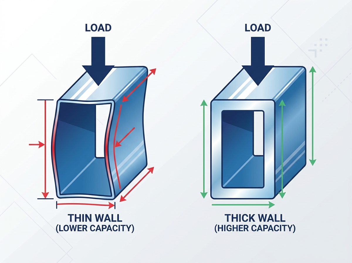
Wall thickness directly contributes to the cross-sectional area of an aluminium hollow profile. Increasing the thickness moves mass further away from the neutral axis. This physical distribution of material dictates the profile's resistance to bending and torsional loads. A larger cross-sectional area provides more material to absorb applied forces.
However, placing that material strategically at the outer edges maximizes the moment of inertia. The moment of inertia is a mathematical representation of how a shape resists bending. Because the formula for moment of inertia involves squaring or cubing the distance from the neutral axis, moving material to the perimeter offers superior rigidity compared to simply making the entire profile thicker or using a solid bar of the same weight.
Profile Size (Square) | Wall Thickness | Relative Cross-Sectional Area | Relative Moment of Inertia (I) | Deflection Resistance |
|---|---|---|---|---|
50mm x 50mm | 2.0 mm | Base Baseline | Base Baseline | Standard |
50mm x 50mm | 3.0 mm | +48% Increase | +42% Increase | High |
50mm x 50mm | 4.0 mm | +92% Increase | +78% Increase | Very High |
Solid 50mm Bar | Solid | +550% Increase | +280% Increase | Maximum (Inefficient) |
You must differentiate between a profile bending under weight and permanently deforming. Deflection occurs when a load causes temporary bowing. Exceeding yield strength causes irreversible damage. Empirical data comparing 1mm versus 3mm profiles illustrates how incremental thickness increases impact these distinct failure modes.
A 3mm profile holds significantly more weight before deflecting compared to a 1mm profile. However, load capacity does not scale in a purely linear fashion. Tripling the wall thickness from 1mm to 3mm often yields a structural rigidity increase far greater than a factor of three due to the exponential nature of the moment of inertia calculations. In field applications, a 1mm wall might deflect 15mm under a 100kg center load, while a 3mm wall of the same outer dimensions might only deflect 2mm under the exact same load. This non-linear relationship is why engineers must calculate the exact section modulus rather than just guessing a thickness.
Manufacturing a hollow aluminum extrusion requires immense pressure. Pushing heated metal through a steel die to create thicker walls increases physical resistance. The die bearing—the flat surface inside the die that controls the metal flow—must be carefully machined to handle this resistance. Added friction requires higher extrusion tonnage from the press. Producing excessively thick profiles can slow down production speeds, strain manufacturing equipment, and require a massive 4000-ton press instead of a standard 2000-ton press.
Wall thickness directly impacts fluid-like aluminum behavior during the extrusion process. Aluminum flows faster through wider die openings and slower through narrow sections. Friction variation between thick and thin zones leads to uneven flow velocities. If a profile has a 6mm wall on one side and a 2mm wall on the other, the metal will surge through the 6mm gap and drag through the 2mm gap. Engineers must utilize specialized die designs, adjusting the bearing lengths to choke the flow on the thick side and speed it up on the thin side. If this balance fails, the profile will exit the die curved or twisted.
Wall thickness choices directly connect to run-out table speeds and cycle times. Thicker profiles retain heat much longer than thin-walled alternatives. Operators must force slower extrusion speeds to avoid thermal tearing, a defect where the surface of the metal literally rips apart as it exits the die due to excessive heat buildup. Maintaining correct metallurgical properties requires careful temperature management. Pushing thick profiles too quickly compromises the structural integrity of the final component and ruins the surface finish.
The thermal dynamics of the extrusion process dictate final part quality. Thick walls retain heat longer than thin walls during the quenching phase. When the profile hits the cooling table, the thin sections cool and contract rapidly, while the thick sections remain hot and expanded. This uneven cooling leads to warping, twisting, and severe difficulty holding tight dimensional tolerances. Consistent cooling ensures the profile remains straight and meets exact engineering specifications.
Bowing: The entire profile curves along its longitudinal axis due to uneven cooling between a thick top wall and a thin bottom wall.
Twisting: The profile spirals along its length, usually caused by asymmetrical wall thicknesses that cool at different rotational rates.
Sink Marks: Slight depressions on the flat outer surface of a profile, occurring exactly opposite an internal thick wall or reinforcing rib that contracted heavily during cooling.
Die Lines: Heavy longitudinal scratches on the surface, often exacerbated by pushing thick, high-friction profiles through the die too quickly.
Engineers follow a strict guideline for profile design to prevent the defects listed above. The minimum wall thickness should always be at least 50% of the thickest area. If your primary load-bearing wall is 8mm thick, no other connecting wall on that profile should be thinner than 4mm. Violating this rule introduces severe structural and manufacturing consequences. Abrupt transitions between thick and thin sections generate internal stress concentrations that lead to premature failure under load. It also makes the profile nearly impossible to extrude straight without extensive post-extrusion stretching and correction.
Load capacity scales differently with wall thickness across standard shapes. Round tubes distribute stress evenly across their entire circumference, making them excellent for torsional (twisting) loads. Square tubes handle multidirectional bending loads well but concentrate stress at the 90-degree corners. An aluminum rectangular profile often requires different wall thicknesses on its vertical versus horizontal axes. You must align the thicker walls parallel to the primary direction of the applied load to maximize bending resistance.
Profile Geometry | Primary Load Strength | Wall Thickness Strategy | Common Application |
|---|---|---|---|
Round Tube | Torsional / Multi-directional | Uniform thickness across circumference | Handrails, fluid transport, axles |
Square Tube | Bi-directional bending | Uniform thickness on all four sides | Machine frames, structural columns |
Rectangular Profile | Single-axis bending | Thicker vertical walls, thinner horizontal walls | Floor joists, roof beams, trailer frames |
Application class dictates wall thickness priorities. Architectural profiles focus heavily on aesthetics, wind loads, and minimal visible deflection. Think of window frames or curtain walls. These applications often utilize thinner walls (typically 1.2mm to 2.0mm) to reduce weight and improve surface finish. Structural and industrial applications prioritize heavy dynamic loads and yield resistance. Think of crane booms or heavy machinery bases. These environments demand thicker walls (often 4.0mm to 12.0mm) and high-strength alloys to prevent catastrophic failure under continuous stress.
Custom profiles subjected to off-center or dynamic loading require specific specification strategies. Universally increasing the outer wall thickness adds unnecessary weight and cost. If a load only hits one side of a profile, thickening the entire tube is highly inefficient. Instead, evaluate the use of internal webbing or reinforcing ribs. These internal structures act as a lighter alternative, providing targeted rigidity exactly where the asymmetrical load applies force. A well-placed 2mm internal diagonal web can often provide more structural stability than increasing the entire outer wall thickness by 3mm.
The choice of alloy fundamentally shifts the required wall thickness. You cannot specify a thickness without first knowing the metal grade.
6061 Alloy: This grade offers higher yield strength (typically around 240-275 MPa in a T6 temper). It is highly suitable for thinner walls under high load conditions. It provides excellent structural reliability for heavy-duty applications. However, it is harder to push through the die, meaning complex shapes with very thin walls might not be extrudable in 6061.
6063 Alloy: This grade delivers superior extrudability and a flawless surface finish. It pushes through the die easily, allowing for intricate details and very thin walls. However, its baseline yield strength is lower (typically around 160-214 MPa in a T6 temper). Achieving equivalent strength to a 6061 profile may require specifying thicker walls to compensate.
Artificial aging plays a critical role in maximizing load capacity. The tempering process, such as applying a T6 temper, alters the metal's grain structure through controlled heating and cooling cycles. This heat treatment significantly increases the yield strength of a specific wall thickness. Proper tempering allows you to specify a thinner wall while maintaining the required structural integrity for demanding applications. An untreated 6061-O profile will bend under a fraction of the load that a 6061-T6 profile of the exact same wall thickness can handle.
Adding millimeter increments to wall thickness drastically impacts project budgets. You must calculate the cost-per-meter increase based on current raw aluminum prices. A profile with a 4mm wall uses twice as much raw material as a profile with a 2mm wall. Increased weight also affects shipping logistics, handling requirements, and final assembly labor. A slightly thicker wall might solve a load problem on paper, but it could render the final product too heavy for practical installation or too expensive for the project budget.
Wall thickness changes directly impact aesthetic qualities. Thick sections cool slower, which can cause the formation of die lines, cooling marks, or a loss of surface flatness. These imperfections impact downstream finishing costs. Achieving a premium anodized or powder-coated finish requires a smooth, uniform surface. If your profile has wildly varying wall thicknesses, the anodizing process may highlight the cooling marks, resulting in a rejected batch of material.
Wall thickness affects all downstream manufacturing processes. You must design the profile for how it will be assembled in the field.
Tapping and Threading: A standard machine screw requires at least three full threads of engagement to hold securely. If your wall is only 1.5mm thick, you cannot tap a reliable thread into it. You must thicken the wall locally where the fasteners will go.
CNC Machining: Walls that are too thin may crush, vibrate, or deform under the pressure of a CNC milling bit. This chatter ruins the cut quality.
Cutting and Sawing: Excessively thick walls increase machining time, slow down saw feed rates, and accelerate tool wear on carbide blades.
Uneven wall thickness design flaws present a major risk. Drastic changes in thickness cause uneven cooling and warping. To mitigate this, standardize wall thicknesses across the profile design where possible. If variations are absolutely necessary for load distribution, use gradual tapers between thick and thin sections rather than sharp 90-degree steps. A smooth, angled transition ensures smooth metal flow and even cooling during the extrusion process, keeping the final part straight.
Overestimating load capacity based on static models is another critical risk. Theoretical CAD and FEA (Finite Element Analysis) simulations often fail to account for dynamic real-world forces, vibration, and metal fatigue over time. To mitigate this, implement physical prototyping and dynamic load testing protocols. Physical tests validate theoretical assumptions and ensure the specified wall thickness performs safely under actual operating conditions. Never rely solely on a computer model when human safety is involved.
Finalize your primary load direction and select the optimal profile geometry before specifying any wall thickness dimensions.
Calculate the required moment of inertia for your maximum acceptable deflection rather than relying solely on the material's yield strength.
Consult directly with your extrusion manufacturer's die engineering team to run flow simulations on any profile featuring varying wall thicknesses.
Specify the 6061-T6 alloy for high-stress structural applications to keep the required wall thickness and overall component weight manageable.
Design gradual tapers into your CAD models when transitioning between thick and thin walls to prevent cooling defects and sink marks.
A: Maximum wall thickness depends on the press tonnage and the circumscribing circle size of the profile. Larger presses handle thicker walls, but extreme thicknesses eventually cause metal flow issues, uneven cooling, and thermal tearing during the quench phase.
A: You calculate load capacity using the section modulus, the specific yield strength of the chosen alloy, and the distance between support spans. These variables determine how much weight the profile holds before deflecting beyond acceptable limits or permanently deforming.
A: Yes, profiles can feature varying wall thicknesses. You must follow the 50% rule, ensuring the thinnest wall is at least half the thickness of the thickest wall. Abrupt transitions risk uneven cooling, warping, and severe dimensional tolerance failures.
A: Yes. Thicker walls retain heat longer during the quenching process. This thermal mass difference leads to visible extrusion lines, cooling marks, or sink marks on the opposite flat surfaces. These defects complicate downstream anodizing or powder coating processes.
A: Internal ribs generally provide a higher strength-to-weight ratio and better dimensional stability than simply thickening the outer walls. Ribs add targeted rigidity without drastically increasing the overall material weight or complicating the extrusion cooling process.