Tel:+86-512-53640771-125 E-mail: export@alumag.com.cn
- All
- Product Name
- Product Keyword
- Product Model
- Product Summary
- Product Description
- Multi Field Search

Views: 0 Author: Site Editor Publish Time: 2026-07-28 Origin: Site


Aerospace and high-performance automotive manufacturers rely heavily on 7000 series aluminum for its exceptional strength-to-weight ratio. The inherent hardness and specific alloying elements of this material present unique challenges when trying to achieve ultra-low surface roughness (Ra) straight off the machine. Machinists often struggle with tool wear and surface tearing, which compromise the final component quality.
Poor surface finishes lead directly to rejected parts, unpredictable fatigue life, and a heavy reliance on expensive, time-consuming secondary operations like manual polishing. Engineers and shop floor managers must balance the need for aggressive cycle times with strict quality assurance surface requirements. Failing to optimize the machining process results in bottlenecks and compromised structural integrity.
Optimizing surface finish requires a systematic approach. By establishing precise control over high-speed machining (HSM) parameters, selecting the right tool geometry, dictating strict toolpath strategies, and applying coolant effectively, shops can minimize the need for post-processing and consistently hit tight Ra tolerances.
High-Speed Machining (HSM) is Critical: Transitioning into the HSM regime consistently decreases surface roughness (Ra) on 7000 series alloys by minimizing built-up edge (BUE) and thermal distortion.
Tool Geometry Overcomes Hardness: Utilizing 2- or 3-flute uncoated or specialized polished-carbide end mills with high helix angles prevents chip packing and galling.
Toolpath Strategy Dictates Finish: Mandating climb milling for all final finishing passes is non-negotiable for achieving a mirror-like top layer.
Material Format Impacts Stability: The baseline grain structure and residual stress of the raw stock—whether utilizing a 7075 aluminum rod or a high strength aluminum extrusion—directly influence machining stability and final surface integrity.
The primary alloying elements in the 7000 series are zinc and magnesium. These additions significantly increase the material's hardness compared to standard 6000 series alloys. While this makes the metal less gummy and less prone to sticking to the cutting tool, it also makes it highly abrasive. Machining this hard alloy requires rigid setups to prevent vibration. You cannot treat it like standard architectural aluminum. The cutting forces required to shear the material are higher, which translates to increased stress on the spindle and the tool holder.
There is a high risk of inducing micro-fractures and surface tearing if feed rates are mismatched with spindle speeds. When the cutting tool drags rather than shears, the abrasive nature of the zinc-magnesium matrix causes the surface to tear. This leaves a dull, rough finish that fails inspection and requires heavy manual rework. We often see operators try to slow down the feed rate to improve the finish, but this actually increases rubbing and heat generation, leading to a smeared surface layer that masks underlying micro-cracks.
Material Comparison: 6061 vs. 7075 Machinability | |||
Property | 6061-T6 Aluminum | 7075-T6 Aluminum | Impact on Surface Finish |
|---|---|---|---|
Primary Alloying Elements | Magnesium, Silicon | Zinc, Magnesium, Copper | 7075 is more abrasive, requiring sharper tooling to prevent tearing. |
Hardness (Brinell) | ~95 | ~150 | Higher hardness in 7075 reduces gumminess but increases tool wear. |
Chip Formation | Continuous, stringy | Shorter, more brittle | 7075 chips evacuate easier, reducing the risk of recutting and scratching. |
Thermal Conductivity | 167 W/m-K | 130 W/m-K | 7075 retains more heat, requiring optimized coolant strategies to prevent warping. |
The starting format of your raw material dictates how it will behave during heavy material removal. A drawn 7075 aluminum rod features a highly uniform grain flow along its longitudinal axis. This uniformity generally provides predictable machining characteristics and stable surface finishes across rotational parts. When turning or milling a rod, the material pushes back against the tool with consistent resistance, allowing for highly dialed-in feed rates and predictable tool life.
Conversely, a high strength aluminum extrusion often contains varying levels of internal residual stress depending on the cooling and stretching processes used at the mill. When you machine away large volumes of an extrusion, these internal stresses release, causing the part to warp. This warping misaligns the part for the final finishing pass, negatively impacting surface quality and dimensional accuracy. To combat this, operators must rough the part, unclamp it to allow the stresses to relieve, and then re-clamp it with minimal pressure for the final finishing operations.
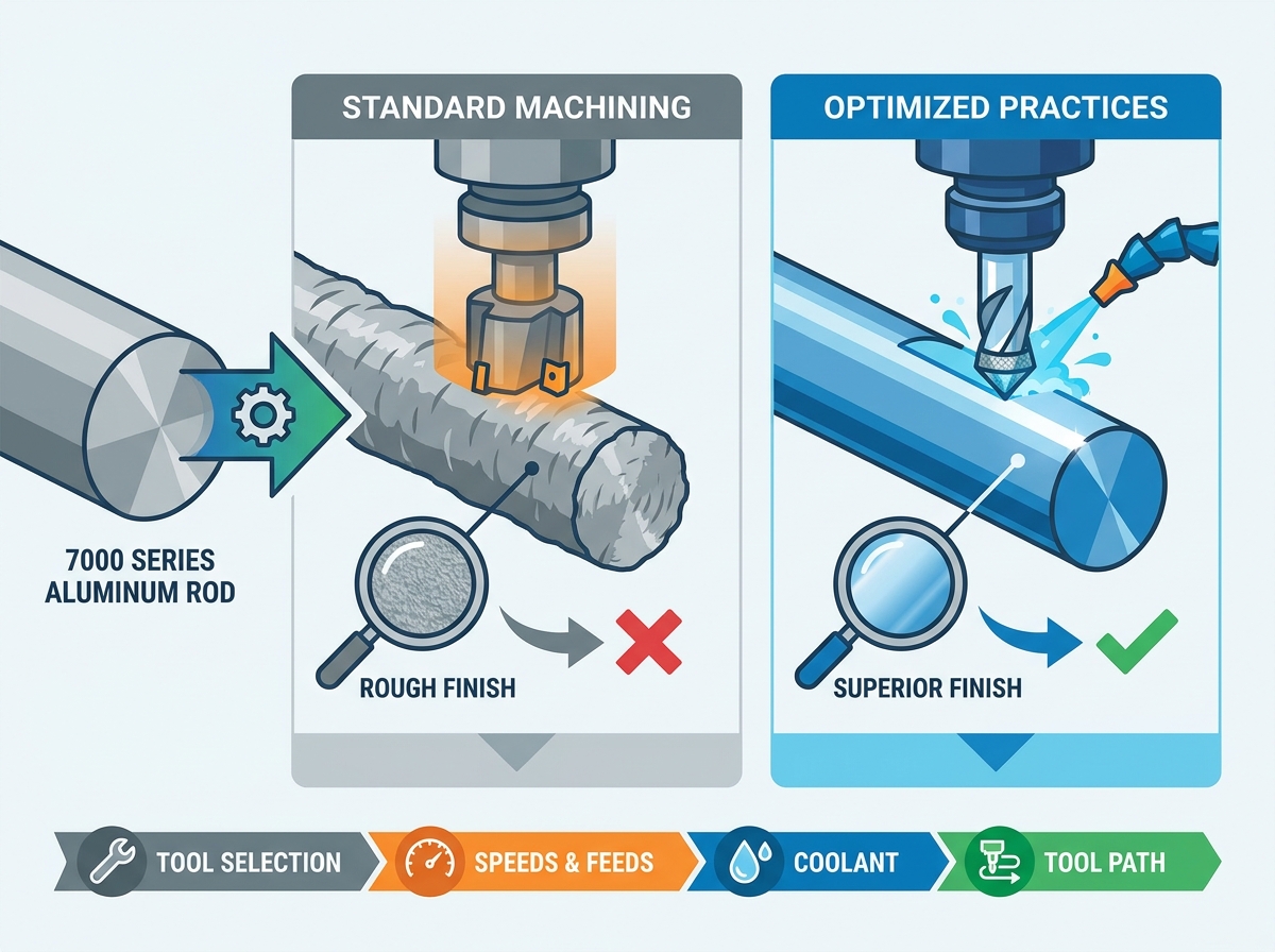
High-Speed Machining (HSM) for 7000 series alloys typically involves running surface feet per minute (SFM) well above conventional limits, often exceeding 1,500 to 3,000 SFM depending on the tooling. Operating in this regime changes the physics of the cut. The heat generated by the shearing action transfers almost entirely into the chip rather than the workpiece or the tool. You need a spindle capable of maintaining high RPMs without introducing runout or vibration, which will immediately transfer to the part surface as chatter marks.
Empirical evidence on the shop floor shows that higher cutting speeds drastically reduce cutting forces. By evacuating heat rapidly through the chip, thermal distortion of the surface is minimized. This consistent thermal management directly translates to lower Ra values and a brighter, cleaner finish. When we push the SFM higher, the material shears cleanly before it has a chance to deform plastically. This is the secret to achieving a mirror-like finish without secondary polishing.
Optimal chip load during finishing passes relies on the principle of chip thinning. You must maintain a feed rate that allows the cutting edge to shear the material cleanly without rubbing. A target chip load for finishing aluminum typically ranges from 0.001 to 0.003 inches per tooth, depending on the tool diameter. If you drop below this threshold, the tool edge rubs the material instead of cutting it. This rubbing action generates massive amounts of heat and causes the material to work-harden instantly.
The trade-off is strict. Feeding too slow causes the tool to rub against the abrasive surface, leading to rapid work hardening, excessive tool wear, and a smeared finish. Feeding too fast increases the cutting pressure, leaves visible scallop marks from the tool radius, and spikes the Ra value beyond acceptable limits. You have to find the sweet spot where the tool is taking a definitive bite out of the material on every pass.
Calculate the base RPM using the recommended SFM for your specific tool coating and diameter.
Determine the target chip load (IPT) based on the desired surface finish and tool geometry.
Calculate the feed rate (IPM) by multiplying RPM by IPT by the number of flutes.
Run a test pass on scrap material and measure the Ra value.
Adjust the feed rate up or down in 5% increments to dial in the optimal finish.
Climb milling is mandatory for all finish passes on aluminum. In climb milling, the cutting tooth enters the material at maximum chip thickness and exits at zero. This directs the cutting forces downward, stabilizing the part and driving heat into the chip. It eliminates the rubbing action that occurs at the start of a conventional milling cut. When you conventional mill, the tool rubs against the surface before it finally bites in, which destroys the surface finish and rapidly dulls the cutting edge.
For tight-tolerance surface requirements, implement spring passes. A spring pass is a zero-stock removal pass where the tool runs the exact same toolpath a second time. This accounts for any tool deflection that occurred during the initial finish pass, ensuring the final surface is perfectly flat and free of taper. We use spring passes extensively on thin-walled aerospace components where tool pressure causes the wall to flex away from the cutter during the initial pass.
Achieving a clean, ridge-free top-layer or floor finish requires precise stepover control. The ideal stepover percentage for a flat end mill or face mill is typically 40% to 60% of the cutter diameter. This overlap ensures that the tool does not leave axial ridge lines while maintaining a consistent cutting pressure. If your stepover is too small, you increase the cycle time unnecessarily and risk rubbing the surface. If it is too large, you leave distinct witness marks between passes.
Implement clean-up passes and custom toolpath strategies like spiral or constant-engagement parallel finishing. These strategies keep the tool in constant motion and prevent dwelling. Tool dwelling leaves distinct witness marks on the surface. Continuous engagement ensures a uniform surface flat across the entire machined area. Modern CAM software allows you to program morphing spiral toolpaths that eliminate sharp directional changes, keeping the tool load perfectly constant.
Selecting between 2-flute and 3-flute end mills depends on the operation. For finishing, 3-flute tools offer a larger core diameter, which increases tool rigidity and reduces chatter. They still provide adequate flute valley space for chip evacuation, making them ideal for profiling and facing. We generally avoid 4-flute tools for aluminum because the flute valleys are too small, leading to chip packing and catastrophic tool failure.
High helix angles, typically between 45° and 55°, are vital for top-layer finishes. A high helix creates a sharper cutting edge that shears the material cleanly with a continuous slicing action. This prevents the tearing and pulling associated with lower helix angles, resulting in a superior surface finish. The high helix also helps to lift the chips up and out of the cut, which is critical when machining deep pockets.
End Mill Selection for 7000 Series Aluminum | |||
Flute Count | Best Application | Pros | Cons |
|---|---|---|---|
2-Flute | Slotting, heavy roughing | Maximum chip clearance, prevents packing. | Lower core strength, prone to deflection. |
3-Flute | Finishing, profiling, high-speed machining | Excellent balance of rigidity and chip clearance. | Slightly less chip room than 2-flute. |
4-Flute (Not Recommended) | Ferrous metals | High rigidity. | Chips pack instantly in aluminum, causing tool breakage. |
A radiused corner tool or an end mill with a specialized wiper flat significantly mitigates micro-grooves on floor surfaces. The radius distributes the cutting forces over a larger area, preventing the sharp corner from digging into the material and leaving a harsh feed line. We always specify a minimum 0.015-inch corner radius for finishing tools unless a sharp internal corner is strictly required by the print.
Sharp-cornered tools are highly susceptible to micro-chipping. When a sharp corner chips, it drags across the surface, leaving deep scratches. Using radiused tools ensures consistent performance and a smoother floor Ra, especially when machining large flat areas. Wiper inserts on face mills take this a step further by utilizing a small flat section parallel to the workpiece to literally wipe away the feed marks left by the leading edge of the insert.
Tool coatings must be evaluated carefully. Standard TiAlN coatings have a high affinity for aluminum. The aluminum literally welds itself to the coating, causing severe galling and destroying the surface finish. Avoid these coatings entirely for this material group. We have seen entire batches of parts scrapped because an operator grabbed a TiAlN coated tool by mistake.
Instead, utilize polished uncoated solid carbide tools. The polished flutes provide high lubricity, allowing chips to slide out of the cutting zone without sticking. If a coating is desired for extended tool life, specify specialized ZrN or TiB2 coatings, which resist built-up edge (BUE) and maintain a razor-sharp cutting edge. These specialized coatings reduce friction and allow you to push the SFM even higher without risking material adhesion.
High-pressure flood coolant physically breaks chips and blasts them out of the cutting zone. This prevents chip recutting, which is a primary cause of deep surface scratching in pockets and cavities. However, flood coolant requires massive infrastructure and fluid maintenance. You have to monitor the concentration, pH levels, and tramp oil contamination daily to ensure the coolant performs as expected.
MQL offers an environmentally friendly alternative by delivering a precise aerosol of oil directly to the cutting edge. While MQL provides excellent lubricity, it lacks the chip-evacuation power of high-pressure flood systems. If using flood coolant, maintain a richer 8% to 10% concentration mix to maximize lubricity during final finishing passes. We use a refractometer every morning to verify the coolant concentration before running any critical finishing operations.
Aggressive machining generates heat that causes thermal expansion in the workpiece. If the part expands during the finish pass and then cools, the final dimensions and surface flatness will warp. This is a critical risk when holding tight tolerances. 7000 series aluminum moves significantly when subjected to thermal gradients, so you have to keep the temperature stable from the start of the cut to the finish.
Mitigate this by maintaining a consistent coolant temperature throughout the machining cycle. Utilize programmable coolant nozzles to ensure the cutting zone remains completely flooded, even during complex 3D surfacing where the tool orientation changes rapidly. Some advanced machines use chiller units on the coolant tank to keep the fluid at a constant 68°F (20°C), which completely eliminates thermal drift during long cycle times.
Manual or vibratory polishing uses abrasive media to physically wear down the surface peaks. While effective, it is inconsistent and can induce mechanical stress or alter critical dimensions on precision components. Operators applying varying pressure with a polishing wheel will inevitably create low spots and ruin the flatness of a precision machined face.
Electropolishing removes a microscopic layer of material electrochemically. It levels micro-peaks to improve Ra without inducing any mechanical stress. This process is ideal for complex geometries and internal cavities where mechanical polishing cannot reach, leaving a bright, passive surface. You have to account for the material removal rate of the electropolishing process during the machining phase, typically leaving an extra 0.0005 inches of material on critical dimensions.
The baseline machined surface finish dictates the cosmetic and functional quality of subsequent anodizing. Type II and Type III hardcoat anodizing will not hide poor machining marks; in fact, the anodizing process often exaggerates them. If you have chatter marks or stepover ridges on the part, they will be glaringly obvious after the anodizing dye is applied.
A torn or chattered surface will result in a dull, uneven anodized layer. Achieving a clean, sheared finish straight off the machine ensures that the anodized coating grows uniformly, providing maximum corrosion resistance and a premium cosmetic appearance. We always aim for an Ra of 32 or better before sending parts out for hardcoat anodizing to ensure a flawless final product.
Chatter marks appear as a distinct wavy pattern on the machined surface. The root causes are typically excessive tool overhang, a lack of rigidity in the workholding setup, or harmonic resonance between the tool and the workpiece. When you hear that high-pitched squeal during a cut, you are generating chatter marks.
To mitigate chatter, minimize tool stick-out. Utilize variable pitch or variable helix end mills. These tools alter the timing of the cutting impacts, breaking up the harmonic resonance and stabilizing the cut. You should also check your workholding to ensure the part is clamped securely close to the cutting zone.
Galling occurs when aluminum welds to the cutting edge, creating a built-up edge (BUE) that tears the workpiece surface. Root causes include inadequate lubricity, using the wrong tool coating, or running at an insufficient SFM. BUE effectively changes the geometry of the cutting tool, turning a sharp edge into a blunt, jagged hammer.
Mitigation steps include increasing the coolant concentration to improve lubricity. Switch to a highly polished, uncoated carbide tool. Finally, increase the spindle speed to generate enough heat in the shear zone to evacuate the chip cleanly before it can adhere to the tool.
Scuffing happens when the trailing edge of the cutter drags across the already machined surface, leaving overlap marks and back-cutting lines. This ruins the visual uniformity of a faced part. It usually indicates that the spindle is not perfectly perpendicular to the machine table.
To fix this, tram the spindle head to ensure absolute perpendicularity to the machine table. Adjust the axial depth of cut to ensure consistent tool pressure. Always utilize balanced, high-precision tool holders to eliminate runout. Shrink-fit tool holders are excellent for this application because they provide massive gripping force with virtually zero runout.
Achieving superior surface finishes requires a holistic approach rather than relying on post-processing. Focus on high-speed machining principles, utilize specialized high-helix and polished tooling, and ensure absolute rigidity in your setups.
Audit your current tooling inventory and replace standard coated end mills with polished uncoated or ZrN-coated carbide for finishing passes.
Implement mandatory climb milling and spring passes in your CAM programming for all tight-tolerance surfaces.
Verify your coolant concentration daily, maintaining an 8% to 10% mix to ensure maximum lubricity.
Tram your CNC spindles regularly to eliminate trailing edge scuff marks on wide face-milling operations.
A: A dull finish usually indicates rubbing rather than shearing. This is caused by feeding too slowly, using a tool with a worn edge, or utilizing an end mill with an inappropriate coating like TiAlN that causes the aluminum to stick.
A: No. 7075 is significantly harder and more abrasive due to its zinc and magnesium content. You typically need to adjust your chip load and ensure highly rigid setups to prevent chatter, which is more likely to occur with harder alloys.
A: MQL provides excellent lubricity but lacks the volume to flush chips out of deep pockets. For deep cavities, high-pressure flood coolant is recommended to prevent chip recutting, which causes deep surface scratches.
A: Ensure your spindle is perfectly trammed. Use an end mill with a corner radius or a wiper flat, and set your stepover between 40% and 60% of the tool diameter. Continuous engagement toolpaths also help eliminate dwell marks.
A: Yes, electropolishing removes a microscopic layer of material, typically between 0.0002 and 0.001 inches. You must account for this material removal in your final machining tolerances before sending the part out for polishing.