Tel:+86-512-53640771-125 E-mail: export@alumag.com.cn
- All
- Product Name
- Product Keyword
- Product Model
- Product Summary
- Product Description
- Multi Field Search

Views: 0 Author: Site Editor Publish Time: 2026-07-28 Origin: Site


As the length of an extrusion increases, the physical forces driving thermal distortion, bowing, flatness deviation, and twisting multiply exponentially. Out-of-tolerance profiles trigger cascading costs across manufacturing operations. Assembly misalignment in modular systems, structural integrity failures, increased scrap rates, and delayed production timelines are direct consequences of poor dimensional control. Precision matters when dealing with long spans where minor deviations compound into major assembly roadblocks. Controlling straightness and twist requires a multi-stage approach. The process ranges from initial simulation-driven die design to advanced post-extrusion stretching. Understanding this workflow provides a framework for evaluating a manufacturer's capability to deliver dimensionally stable long profiles. Achieving tight tolerances demands specialized equipment, strict thermal management, and robust quality assurance protocols. You cannot simply push metal through a die and expect a perfectly straight 20-foot section without engineering the entire thermal and mechanical lifecycle of that specific shape.
Die Design is the First Line of Defense: Effective control begins before the press; FEA simulation and balanced metal flow through the die prevent the uneven cooling and velocity differentials that cause initial twist.
Post-Extrusion Stretching is Mandatory: Achieving standard straightness requires stretching the profile by 1% to 3% past its yield point immediately after the cooling table using advanced multi-axis stretchers.
Profile Geometry Dictates Correction Methods: The techniques used to straighten a solid aluminum extrusion differ significantly from those required for complex, multi-void hollow profiles or high-precision modular framing profiles.
Flatness, Straightness, and Twist Are Interconnected: Controlling dimensional stability requires addressing all three phenomena simultaneously through die design, quenching, and roller correction.
Tolerance Specifications Drive Cost: Specifying tolerances tighter than standard industry benchmarks (e.g., standard Aluminum Association tolerances) requires specialized multi-axis correction equipment (up to eight-axis control) and increases per-unit costs.
Dimensional defects in aluminum extrusion profiles manifest in three primary ways. Straightness, often referred to as bow or camber, is the longitudinal deviation from a perfectly straight line. Twist is the rotational or angular distortion along the longitudinal axis. Flatness represents the transverse deviation across the surface of a single face. These three factors determine the overall dimensional stability of the extruded metal. When you measure a profile on a surface plate, you are looking for how far it lifts off the table. A profile might be perfectly flat on one face but bow significantly over a 10-foot span. Understanding the distinction between these defects dictates the correction method applied on the shop floor.
Defect Type | Definition | Primary Cause | Measurement Method |
|---|---|---|---|
Straightness (Bow/Camber) | Longitudinal deviation from a straight line. | Uneven pulling tension, asymmetrical cooling. | Feeler gauges along a precision straightedge. |
Twist | Rotational distortion along the longitudinal axis. | Unbalanced metal flow through the die, uneven quenching. | Inclinometer or height gauge on a surface plate. |
Flatness | Transverse deviation across a single face. | Die deflection, improper roller correction. | Straightedge placed across the profile width. |
Deformation stems from residual stresses introduced during the extrusion and cooling phases. Uneven cooling rates across varying wall thicknesses cause different sections of the profile to contract at different speeds. Asymmetrical profile cross-sections naturally cool unevenly, exacerbating this issue. Furthermore, inconsistent puller tension on the runout table can introduce mechanical stresses before the metal has fully hardened. If a profile has a thick base and thin fins, the fins cool rapidly while the base retains heat. This thermal gradient forces the metal to warp as it shrinks. Managing this gradient requires precise control over the quenching environment.
Profiles over standard lengths, such as those exceeding 20 feet, are disproportionately susceptible to deformation. Gravity-induced sag becomes a significant factor as the hot, pliable metal travels down the runout table. Thermal warping during the quenching phase is also magnified over long spans. The longer the profile, the harder it is to maintain uniform cooling and tension, increasing the likelihood of twist and bow. A deviation of 0.010 inches per foot might seem negligible on a short bracket. Over a 24-foot span, that same deviation results in nearly a quarter-inch of bow, rendering the part useless for precision applications.
Minor twist or straightness deviation in specialized profiles makes assembly nearly impossible. For example, 15-series and 40-series T-slot framing systems rely on precise alignment of connection channels. If a long profile exhibits even slight bowing, the T-nuts and brackets will not slide smoothly or seat correctly. This misalignment compromises the structural integrity of the entire modular assembly. Field installers waste hours attempting to force warped profiles into alignment. In many cases, the stress applied to force the connection causes premature failure of the joint under dynamic loads.
Effective control begins with optimizing metal flow for a custom aluminum extrusion profile. Finite Element Analysis (FEA) and numerical exit flow simulation models predict exit velocity and potential twist defects before cutting the die steel. By simulating the extrusion process, engineers can identify flow imbalances and correct them in the design phase. This predictive modeling saves countless hours of trial and error on the press.
Analyze the cross-sectional geometry for varying wall thicknesses.
Run FEA simulations to map expected metal flow velocities.
Adjust die bearing lengths to choke or accelerate flow in specific zones.
Simulate the quenching process to predict thermal distortion.
Finalize the die design and cut the steel.
Die bearing length adjustments are necessary to ensure uniform exit velocity across asymmetrical cross-sections. Longer bearings slow the metal flow, while shorter bearings allow it to move faster. Balancing these lengths ensures the profile exits the die straight. Effective die maintenance, repair, and polishing prevent localized friction, which can cause uneven flatness and surface defects. A poorly maintained die with worn bearings will inevitably produce twisted profiles, regardless of downstream correction efforts.
Maintaining consistent extrusion pressure and exit temperatures requires precise billet temperature management. Taper heating the billet ensures a temperature gradient from the front to the back. This gradient compensates for the heat generated by friction during extrusion, keeping the exit temperature uniform throughout the entire length of the profile. Consistent temperature minimizes thermal variations that lead to warping. If the billet is heated uniformly, the back end will extrude much hotter than the front end due to accumulated friction heat. Taper heating solves this problem by starting the back end cooler.
Automated pullers play a crucial role on the runout table. They maintain constant, synchronized tension on the profile as it exits the press. This tension prevents the hot metal from snaking or buckling. Consistent pulling force is essential for keeping long profiles straight before they reach the cooling phase. The puller must match the exit speed of the press exactly. If it pulls too hard, it stretches the hot metal out of tolerance. If it pulls too slowly, the metal bunches up and buckles.
Quenching protocols must be uniform to prevent thermal stress. Whether using forced air, water mist, or full water quenching, the cooling medium must hit all surfaces evenly. Asymmetrical quenching on complex geometries locks in thermal stress and guarantees twist. Careful nozzle placement and volume control are critical for balanced cooling. For heavy solid shapes, a full water quench might be necessary to achieve mechanical properties. For thin-walled hollows, aggressive water quenching often causes severe distortion, requiring a gentler air quench.
Position air nozzles to target thicker sections of the profile.
Adjust water mist volume based on the alloy and extrusion speed.
Monitor profile temperature continuously along the runout table.
Ensure the cooling bed supports the profile evenly to prevent sagging.
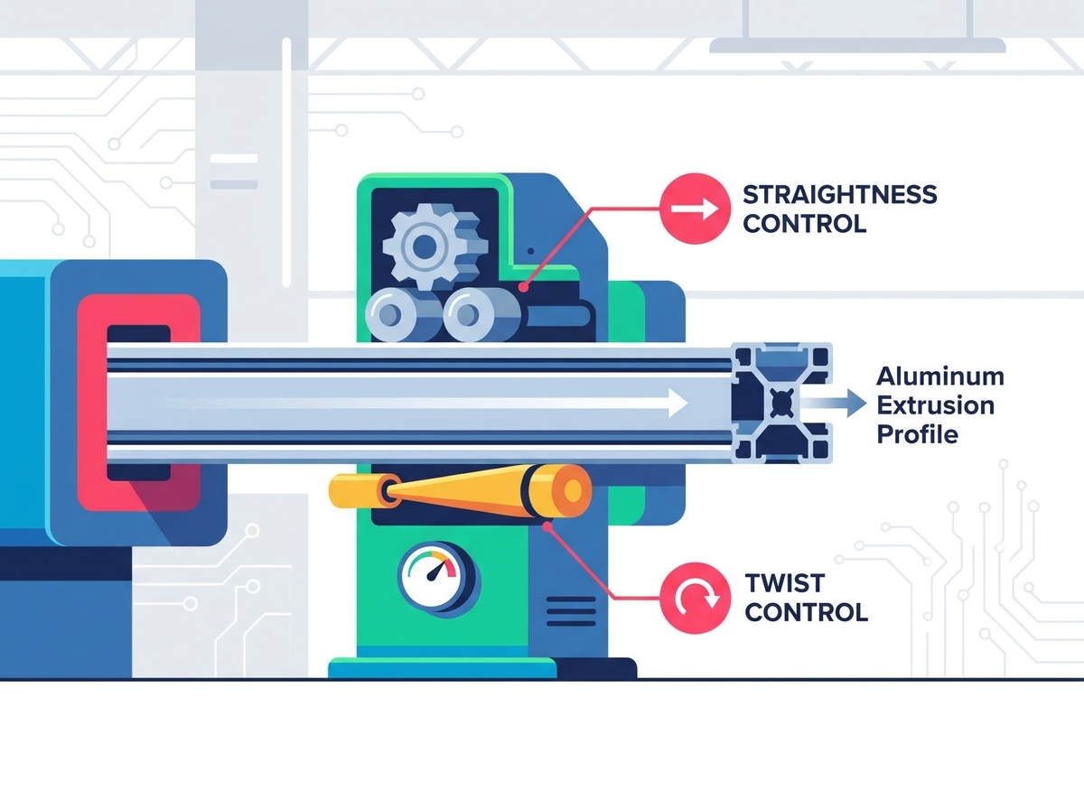
Real-time side roller adjustments at the press exit help mitigate initial twist and bow defects. Guided by simulation exit-direction parameters, these rollers apply gentle pressure to correct the profile before the metal fully cools. This online correction reduces the burden on post-extrusion stretching equipment. Operators monitor the profile as it exits the die and make micro-adjustments to the guide rollers. This proactive approach prevents severe distortion from setting in during the initial cooling phase.
Moving profiles to a stretcher to apply a 1% to 3% longitudinal stretch is a standard industry practice. This process induces yield point deformation. The plastic deformation relieves residual internal stresses and aligns the grain structure. Stretching is mandatory for achieving standard straightness tolerances in long profiles. The stretcher grips both ends of the profile and pulls it until it yields slightly. This action snaps the metal into a straight line and locks in the dimensional stability.
Complex geometries require advanced stretching equipment. Modern stretchers feature up to eight independently controlled axes and multiple die tables. These machines can simultaneously pull, lift, and untwist long profiles. This level of control is necessary for correcting severe twist and bow in asymmetrical designs. A standard stretcher only pulls in one direction. A multi-axis stretcher can rotate the jaws to counteract twist while simultaneously applying longitudinal tension. This capability is essential for high-precision architectural and aerospace components.
Profiles that fail to meet flatness or straightness tolerances after initial stretching undergo secondary correction. Multi-roll straighteners apply localized pressure to correct specific deviations. This off-line roller shape correction is often required for high-precision applications demanding tight tolerances. The profile passes through a series of staggered rollers that bend the metal slightly past its yield point in alternating directions. This process gradually works out localized bows and kinks.
Correction limits vary based on profile geometry. A solid aluminum extrusion can generally withstand aggressive roller correction. In contrast, thin-walled hollow profiles risk crushing, sagging, or internal web distortion under similar loads. Hollows require more delicate handling and precise stretching parameters. You can push a solid bar through a heavy-duty roller straightener without issue. If you try the same process on a thin-walled rectangular tube, the rollers will crush the side walls and ruin the part.
Auditing a supplier requires assessing their equipment capabilities. Ensure they possess stretchers rated for the tonnage required by your profile's cross-sectional area and length. Verify if they utilize multi-axis stretchers with multiple die tables for complex corrections. Adequate equipment is the foundation of dimensional stability. A supplier with a 1000-ton press but only a basic single-axis stretcher will struggle to deliver straight 24-foot profiles. You must match the supplier's equipment to your specific tolerance requirements.
Verify straightness using calibrated straightedges and feeler gauges on certified flat inspection tables. Advanced measurement standards include laser scanning systems and coordinate measuring machines (CMM) for long spans. Robust QA protocols ensure the final product meets specified tolerances. Relying on visual inspection is inadequate for long spans. The supplier must have the metrology equipment necessary to quantify deviation over the entire length of the extrusion.
Compare standard Aluminum Association tolerances with precision requirements. Define acceptable deviation per foot or meter of length. Discuss these tolerance capabilities with potential partners to ensure they can meet your specific project needs without excessive scrap rates. Standard tolerances might allow for 0.0125 inches of bow per foot. If your application requires 0.005 inches per foot, you must specify this upfront and ensure the supplier has the capability to achieve it.
Tolerance Standard | Typical Bow Allowance (per foot) | Typical Twist Allowance (per foot) | Application Suitability |
|---|---|---|---|
Standard Aluminum Association | 0.0125 inches | 0.5 degrees | General construction, non-critical framing. |
Precision Commercial | 0.005 - 0.010 inches | 0.25 degrees | Modular framing, automated machinery bases. |
Ultra-Precision (Custom) | < 0.005 inches | < 0.1 degrees | Aerospace, optical mounting rails, linear guides. |
Demanding zero-deviation straightness on long profiles creates an exponential cost curve. Tighter tolerances lead to increased scrap, slower run speeds, and secondary manual operations. Balancing precision requirements with budget constraints is necessary for cost-effective manufacturing. Every time you cut a tolerance in half, you potentially double the manufacturing cost. You must evaluate whether the application truly requires ultra-precision or if the design can accommodate standard deviations.
Harder alloys, such as the 7000 series, present higher resistance to post-extrusion straightening compared to softer alloys like 6063. This resistance impacts the feasibility of achieving tight tolerances. Alloy selection must consider both mechanical properties and manufacturability. A 7075 alloy profile will require significantly more stretching tonnage to yield than a 6063 profile. If the stretcher lacks the necessary capacity, the harder alloy will retain its twist and bow.
Modifying the profile design reduces the need for aggressive post-extrusion correction. Adding symmetry, balancing wall thicknesses, and incorporating generous corner radii improve dimensional stability. Design-for-Manufacturability (DFM) compromises lower costs and increase production consistency. A highly asymmetrical profile with massive variations in wall thickness is a nightmare to extrude straight. By working with the extrusion engineer to balance the cross-section, you eliminate the root cause of the distortion.
Reviewing the design for potential thermal imbalances before cutting the die saves significant time and money. Simple changes, like adding a hollow void to a thick section to equalize cooling rates, drastically improve the final straightness of the part. The goal is to design a shape that naturally wants to extrude straight, rather than relying entirely on brute force correction after the fact.
Audit your current profile designs to identify asymmetrical features or extreme wall thickness variations that contribute to thermal distortion.
Define your exact straightness and twist tolerance requirements per foot based on actual assembly needs, rather than defaulting to overly strict specifications.
Request equipment lists from potential extrusion partners to verify they possess multi-axis stretchers capable of handling your profile's length and cross-sectional area.
Initiate a technical DFM consultation with your extrusion manufacturer to balance metal flow and optimize the die design before production begins.
A: Straightness is measured using a precision straightedge or layout table. The profile is placed on a flat surface, and feeler gauges measure the maximum gap (bow or camber) along the length. This is typically calculated as deviation per foot or meter of total length.
A: Straightness measures longitudinal deviation (bowing). Twist measures rotational deviation along the length axis. Flatness measures localized transverse deviation across a single flat surface profile face.
A: Standard tolerances depend on the profile's circumscribing circle size and alloy. They generally allow for a specific degree of twist per foot (e.g., 0.5 degrees per foot), capping at a maximum total twist for the full length.
A: Warping is caused by residual stresses from uneven cooling rates across different wall thicknesses or asymmetrical geometries during the quenching process.
A: Minor corrections can be made via off-line roller straightening or annealing. However, severe twist in fully artificially aged (T6) profiles is highly difficult to correct without risking structural failure or cracking.
A: No. Controlled stretching of 1% to 3% past the yield point relieves internal stresses and straightens the profile. It is a necessary step in achieving the final mechanical properties and dimensional stability before artificial aging.