Tel:+86-512-53640771-125 E-mail: export@alumag.com.cn
- All
- Product Name
- Product Keyword
- Product Model
- Product Summary
- Product Description
- Multi Field Search

Views: 0 Author: Site Editor Publish Time: 2026-08-05 Origin: Site


Torsional deflection in structural assemblies presents a severe engineering challenge, particularly where rotational forces compromise precision, alignment, or load-bearing integrity. When a framework twists under dynamic loads, it directly degrades the operational accuracy of the entire mechanical system. Engineers constantly face the tension between strict lightweighting mandates and the absolute necessity for high dynamic stiffness. Relying solely on heavier materials or solid cross-sections negates the primary advantage of utilizing lightweight metals in the first place.
Torsional rigidity is primarily governed by cross-sectional geometry rather than material selection alone. By evaluating specific design modifications and extrusion features, engineers can optimize stiffness-to-weight ratios without adding unnecessary mass. This article examines the geometric principles, structural features, and manufacturing considerations required to maximize twist resistance in an aluminium hollow profile.
Geometry Over Material: Increasing the polar moment of inertia through strategic cross-sectional design yields exponentially higher torsional stiffness than changing aluminum alloys.
Closed Sections Dominate: A continuous, closed perimeter is the baseline requirement for resisting applied torque, significantly outperforming open "C" or "I" channels.
Strategic Mass Distribution: Placing material furthest from the centroid (the axis of twist)—such as corner-bulge reinforcements—maximizes rigidity without unnecessary weight penalties.
Dual-Purpose Ribbing: Internal ribs and external flanges not only resist cross-sectional distortion but also assist in post-extrusion straightening operations to minimize manufacturing twist.
Extrudability Constraints: Complex internal ribbing or excessive wall thickness variations must be balanced against extrusion die limitations and manufacturing costs.
Torsional rigidity is mathematically defined as the product of a material's shear modulus and the cross-section's polar moment of inertia. For non-circular sections, engineers use the torsional constant. Aluminum inherently possesses a low shear modulus of approximately 26 GPa, which is significantly lower than structural steel at roughly 80 GPa. This material deficit explains why geometric design must heavily compensate when replacing steel components with lightweight alternatives. You cannot simply swap a steel beam for an aluminum one of the exact same dimensions and expect the same resistance to twist.
The shear modulus remains relatively constant across different structural aluminum alloys. Upgrading from 6061-T6 to 7075-T6 increases yield strength but does virtually nothing to improve baseline stiffness against twist. Consequently, the cross-sectional geometry becomes the primary variable engineers can control. Alongside the polar moment of inertia, the section modulus dictates how torsional shear stress distributes across the profile boundary, determining where material is most needed to prevent deformation. When you design a custom extrusion, you are essentially manipulating these geometric properties to fight the material's natural flexibility.
Understanding shear flow is critical here. Shear flow represents the shear force per unit length along the perimeter of a thin-walled section. In a closed tube, this flow travels continuously around the perimeter. If you break that perimeter, the shear flow must reverse direction, dropping the torsional constant by orders of magnitude. This is the fundamental physics reason why closed shapes are mandatory for high-torque applications.
Torsional stiffness proves critical in high-speed linear guide modules and machine tool axes that undergo continuous movement of large masses. When a gantry system accelerates, eccentric loads apply torque directly to the supporting framework. If the underlying structure lacks adequate rigidity, the resulting twist propagates through the entire mechanical assembly. A heavy spindle motor hanging off the Z-axis creates a massive moment arm. As the X-axis moves, that moment arm tries to twist the main gantry bridge.
The consequences of torsional deflection are severe. Even microscopic angular displacement causes linear rail misalignment. This misalignment increases friction, accelerates wear on bearing blocks, and ultimately destroys positioning accuracy. In precision automation, a framework that twists under load renders high-resolution encoders and precision ball screws ineffective. You might have a linear encoder capable of 1-micron resolution, but if the beam it mounts to twists by 50 microns under dynamic load, your actual tool center point is completely out of tolerance.
Furthermore, torsional vibration can induce chatter during machining operations. When the structure lacks dynamic stiffness, the cutting forces excite the natural frequencies of the twisted beam. This leads to poor surface finishes on machined parts and rapid tool wear. Stiffening the profile against torsion pushes these natural frequencies higher, out of the range of typical operating vibrations.
To evaluate structural integrity, engineers must quantify acceptable angular deflection per unit length based on specific application requirements. A CNC linear module demands exponentially tighter deflection limits than standard architectural framing. Establishing these limits early prevents both under-engineering and costly over-engineering. You need to know exactly how many microradians of twist are acceptable per meter of extrusion under your maximum expected torque load.
The stiffness-to-weight ratio serves as the ultimate evaluation metric for any structural component. The goal is to achieve the required angular stability while minimizing mass. Evaluating this ratio ensures that design additions, such as internal webs or thicker walls, actually provide a proportional benefit to the system's overall performance. Adding 5 kilograms of aluminum per meter to gain a 2% increase in stiffness is a poor design choice. Adding 1 kilogram per meter in the exact right locations to gain a 40% increase is excellent engineering.
Engineers typically use finite element analysis (FEA) to simulate these conditions before cutting a die. By applying a known torque to the digital model of the extrusion, you can visualize the shear stress distribution and measure the angular deflection. This allows for rapid iteration of wall thicknesses and rib placements to hit the target success criteria before committing to physical manufacturing.
Circular tubes offer the highest theoretical torsional efficiency due to their uniform shear stress distribution. Every point on the perimeter sits at an equal distance from the centroid, maximizing the polar moment of inertia for a given amount of material. However, circular profiles are often impractical for mounting flat linear rails or mating with orthogonal structural components. You cannot easily bolt a flat linear guide block to a round tube without secondary machining operations.
When evaluating an aluminum rectangular profile, aspect ratios heavily influence twisting resistance. Square profiles generally resist torsion better than highly elongated rectangles because the shear flow remains more consistent around the perimeter. As a rectangle becomes wider and flatter, its torsional constant drops significantly compared to a square of the same cross-sectional area. Regardless of the specific shape, closed profiles fundamentally prevent warping deformation. A continuous outer wall forces shear stresses to flow in a closed loop, drastically outperforming open sections like "C" channels with similar cross-sectional areas.
Profile Shape | Torsional Efficiency | Mounting Practicality | Best Application |
|---|---|---|---|
Circular Tube | Maximum | Poor | Drive shafts, standalone columns |
Square Tube | High | Excellent | Machine frames, multi-axis joints |
Rectangular Tube (2:1) | Moderate | Excellent | Gantry bridges, long unsupported spans |
Open C-Channel | Very Low | Good | Light duty covers, non-structural trim |
Maximizing torsional resistance requires moving mass as far away from the neutral axis as possible. Material located near the centroid contributes very little to the polar moment of inertia. By shifting wall thickness to the outer perimeter, designers increase the torsional constant efficiently. Think of a figure skater spinning; extending their arms slows them down because the mass moves away from the center of rotation. In structural design, moving mass away from the center resists the twist.
Uniformly increasing wall thickness across the entire profile yields diminishing returns. It adds significant weight without optimizing the stiffness-to-weight ratio. Targeted thickening at high-stress zones, particularly at the furthest boundaries of the cross-section, provides a much higher return on investment for rigidity. If you have a 100x100mm square profile, making all four walls 10mm thick is less efficient than making the walls 5mm thick but adding heavy 15x15mm solid blocks of material at the four extreme corners.
You must also consider the shear center of the profile. For symmetrical shapes, the shear center aligns with the centroid. For asymmetrical shapes, applying a load away from the shear center induces twist even if the load is purely vertical. Designing symmetrical profiles whenever possible eliminates this parasitic torsion, simplifying the overall machine design.
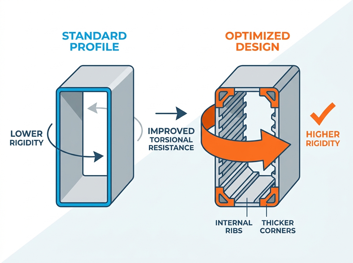
Internal diagonal webs or "X" braces prevent cross-sectional distortion under heavy torque. When a hollow shape twists, the walls tend to cave inward or bulge outward. Internal bracing locks the walls in place, maintaining the geometric integrity of the outer perimeter. Without these ribs, a thin-walled square tube will deform into a rhombus shape before it actually twists along its length.
Compartmentalizing a single hollow void into a multi-void hollow aluminum extrusion significantly boosts performance. Each internal wall acts as an additional shear web. Furthermore, integrating external flanges and supporting members increases the section modulus. These external protrusions enhance overall bending and torsional coupling resistance, providing robust mounting points that inherently stiffen the structure.
Identify the primary axis of applied torque in your assembly.
Place internal webs perpendicular to the expected wall deformation.
Use multi-void designs to break large open spans into smaller, rigid cells.
Add external flanges only where they serve a dual purpose for mounting and stiffening.
Stress concentrations naturally occur at sharp internal corners during torsion, frequently leading to localized shear failure. Sharp transitions disrupt the smooth flow of shear forces around the profile. When torque is applied, the material at a sharp 90-degree internal corner experiences massive stress spikes, which can initiate fatigue cracks over thousands of machine cycles.
Implementing specific corner gusseting and generous internal radii distributes shear flow continuously around the perimeter. Adding localized material mass to the extreme outer corners—often referred to as corner "ears" or "bulges"—places material furthest from the center of twist. This specific design tactic yields the highest possible increase in polar moment of inertia per unit area. A 5mm internal radius is vastly superior to a 1mm radius, and it also helps the aluminum flow through the extrusion die much more easily.
Designing for maximum rigidity must align with the realities of die design. Complex internal ribs and multi-void hollows increase die wear, require higher extrusion pressure, and elevate the risk of internal defects. A die with too many delicate features will fail prematurely. The steel tongues inside the die that form the hollow voids must withstand immense pressure from the flowing aluminum. If you design internal ribs that are too thin, those steel tongues will snap during the extrusion process.
Engineers must balance adjacent wall thicknesses to prevent warping. Extreme thick-to-thin transitions cause uneven material flow and differential cooling rates. If a heavy corner bulge connects to a paper-thin side wall, the profile will likely distort as it exits the extrusion press. The thick corner retains heat longer than the thin wall, causing the profile to bow or twist as it cools on the run-out table. A general rule of thumb is to keep the ratio of thickest to thinnest walls below 2:1.
You also have to consider the circumscribing circle size (CCD). The entire profile must fit within the diameter of the extrusion press container. Pushing a massive, highly ribbed profile requires a massive press, which limits the number of extrusion plants capable of producing your design. Keeping the profile compact while maximizing internal geometry is the true test of extrusion design.
Every geometric addition carries a weight penalty. Designers need a framework to evaluate whether a 10% increase in mass via internal ribbing justifies the resulting percentage increase in torsional stiffness. You cannot just add material blindly; you must track the mass per meter.
Design Modification | Estimated Weight Increase | Estimated Torsional Rigidity Gain | Manufacturability Impact |
|---|---|---|---|
Uniform Wall Thickening | High (20-30%) | Moderate (15-20%) | Low (Easy to extrude) |
Internal Diagonal Bracing | Moderate (10-15%) | High (25-40%) | Moderate (Requires multi-void die) |
Corner Bulges / "Ears" | Low (5-8%) | High (20-30%) | Moderate (Cooling variations) |
Generous Internal Radii | Very Low (1-3%) | Low (Improves fatigue life) | Positive (Improves die flow) |
Using the table above, you can see that corner bulges offer the best ratio of rigidity gain to weight increase. Internal diagonal bracing is also highly effective but requires a more complex multi-void die. Uniform wall thickening is the lazy approach; it works, but it results in a heavy, inefficient structure.
Developing a highly optimized, custom profile requires upfront investment in extrusion dies. Engineers must compare these tooling costs against the performance limitations of utilizing off-the-shelf heavy-duty extrusions. For high-volume production or precision machinery, the performance gains of a custom multi-void profile easily offset the initial die fabrication expenses. A custom die might cost a few thousand dollars, but if it saves you two kilograms of aluminum per meter on a machine you build hundreds of times a year, the payback period is incredibly short.
Furthermore, a custom profile allows you to integrate mounting features directly into the shape. You can extrude T-slots, screw bosses, and locating grooves right into the rigid structure. This eliminates secondary machining operations, saving massive amounts of assembly time and machining costs. The initial die cost is negligible compared to the labor savings on the factory floor.
A highly rigid profile is completely useless if the mechanical joints allow rotational slip. Brackets, bolts, and welds often represent the weakest link in a structural assembly. If the connection points flex, the overall system loses its torsional stability regardless of the profile's geometry. You can design the stiffest beam in the world, but if you bolt it to a frame using a flimsy stamped steel bracket, the assembly will twist at the joint.
To mitigate this, incorporate design features that physically aid assembly and lock joints in place. Integrated fastener channels, precision T-slots, or locating features prevent rotation at the nodes. Using dowel pins or interlocking tabs ensures that torque transfers seamlessly from one structural member to the next without relying solely on friction from bolted connections. Machining a pocket into the mating part so the extrusion sits inside a physical shoulder provides a mechanical stop against rotation.
When using bolts, ensure adequate preload. Torsional loads will try to pry the joint apart. Using high-tensile fasteners and thick, rigid gusset plates helps transfer the shear forces across the joint boundary. Avoid relying on single-bolt connections in any application subject to torque; always use a wide bolt pattern to create a resisting moment arm.
Standard extrusion tolerances for straightness and twist may not meet the demands of precision linear motion systems. Designers must specify precision tolerances when ordering, understanding that tighter tolerances require stricter process controls at the extrusion plant. Standard commercial tolerances might allow for 1 degree of twist per meter. In a CNC gantry, that is completely unacceptable. You must specify half or quarter standard tolerances and work with the extruder to ensure they can meet them.
Internal and external structural ribs physically aid in the post-extrusion straightening operation. After the profile leaves the press, it undergoes tension stretching to correct minor deviations. Well-placed ribs provide the necessary longitudinal strength to withstand this stretching process, effectively reducing residual twist and improving face flatness across the final product. If a profile is too thin and lacks internal support, the stretching jaws will simply crush the ends, and the profile will tear before it straightens.
Secondary machining is often required for critical mounting surfaces. Even the best extrusion process cannot achieve the flatness required for precision linear rails. Design your profile with extra material thickness on the faces where rails will mount. This allows you to fly-cut the surface perfectly flat on a mill without compromising the structural wall thickness.
To maximize torsional rigidity in your next structural design, implement the following steps:
Prioritize closed, multi-void cross-sections over open channels to force shear stresses into continuous loops.
Shift mass to the extreme outer corners of the profile to exponentially increase the polar moment of inertia.
Incorporate internal diagonal webbing to prevent cross-sectional distortion under heavy torque loads.
Specify generous internal radii to eliminate stress concentrations and improve material flow during extrusion.
Design interlocking joint features directly into the profile to prevent rotational slip at assembly nodes.
A: Aluminum has a shear modulus of roughly 26 GPa, compared to steel's 80 GPa. Because the material itself is inherently less stiff against shear forces, aluminum profiles require optimized, closed geometries to match the torsional resistance of steel components.
A: No. Upgrading to a higher-strength alloy like 7075-T6 increases yield strength but does not significantly change the shear modulus. To improve stiffness against twist, you must change the cross-sectional geometry.
A: A circular hollow tube provides the highest torsional rigidity per unit of weight because shear stress distributes uniformly around the perimeter. For mounting purposes, square hollow profiles offer the best practical alternative.
A: Internal ribs provide longitudinal strength. During the post-extrusion tension stretching process, these ribs help the profile resist localized warping, resulting in better overall straightness and reduced residual twist.
A: Sharp internal corners create severe stress concentrations during torsion. Adding generous radii allows shear forces to flow smoothly around the profile perimeter, preventing localized shear failure and improving die life during extrusion.